Read next
Analysis, Design and Implementation of Control System for Warehouse-type Intelligent Robotic Parking Equipment
Abstract : This paper mainly introduces the main mechanical structure of the warehouse-type robot parking equipment and ...
Articles
2026-02-22

CATDOLL Maruko 88CM TPE Doll
Articles
2026-02-22
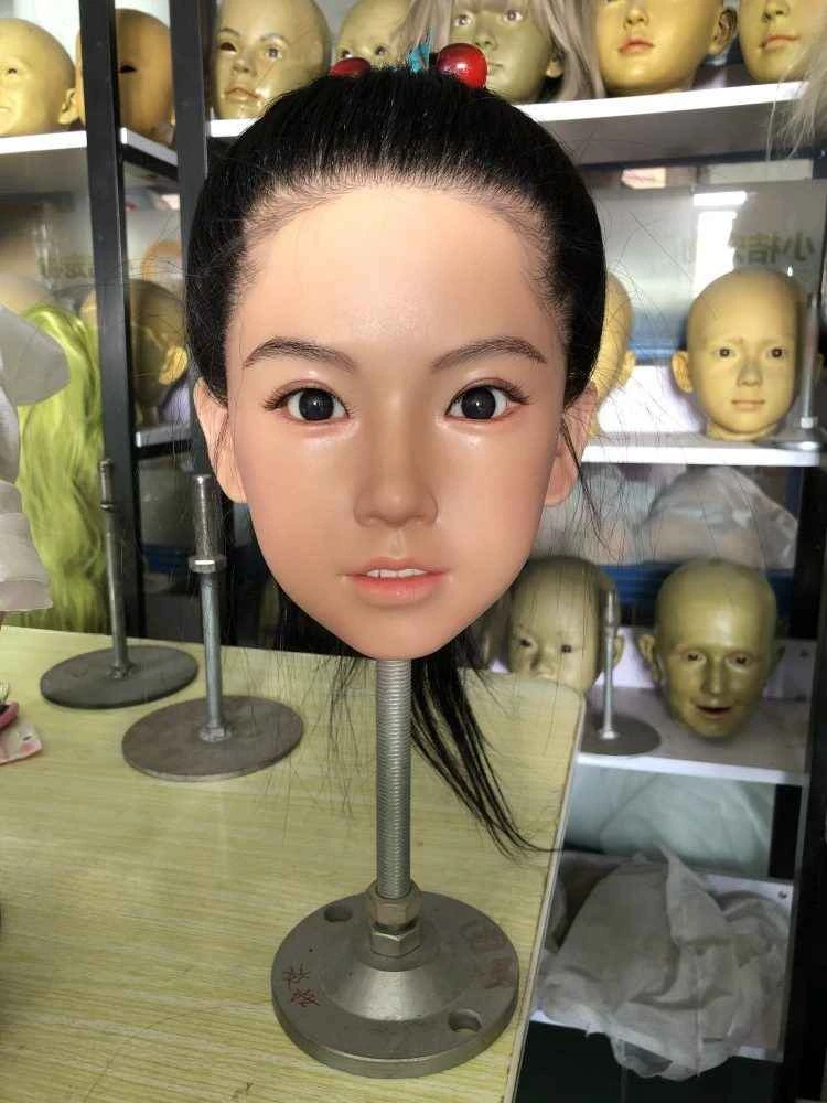
CATDOLL Vivian Hard Silicone Head
Articles
2026-02-22

CATDOLL Q 108cm Natural Tone
Articles
2026-02-22