Share this

Design of the electrical system for a steel ball vibration measuring instrument

2026-04-06 06:00:59 · · #1
Introduction With the development of microelectronics technology, many powerful integrated circuit chips have emerged. These chips can often integrate a complete circuit, several related circuits, or even a complete measurement and control circuit onto a single chip. In the development and design of modern instruments, integrated devices should be used as much as possible. The electrical system design of the steel ball vibration measuring instrument fully utilizes highly integrated chips to simplify circuit design, employing integrated state variable filters, integrated true RMS and logarithmic converters, and integrated function generators, thereby improving the performance of the instrument's electrical system and reducing costs. 1 Working Principle The steel ball under test is fixed to a high-precision spindle and rotates using different fixtures. An accelerometer contacts the surface of the steel ball and picks up the weak vibration signal generated by the ripples on the surface. This signal is amplified by a charge amplifier, passed through a 170–400Hz or 400–800Hz bandpass filter, and then sent to the RMS and logarithmic circuits. Finally, the meter indicates the ripple vibration value of the steel ball under test, the magnitude of which is measured in decibels. The instrument is equipped with a self-calibration circuit, which generates 260Hz and 520Hz sine wave signals for calibration at any time. The measurement principle of the electrical system is shown in Figure 1. 2 Design of Main Unit Circuits 2.1 Preamplifier Circuit The vibration pickup of the steel ball vibration measuring instrument is a piezoelectric accelerometer. There are three structural forms of this type of sensor: peripheral compression, central compression, and shear type. Considering performance and economy, the YD-12 type central compression sensor is selected. The piezoelectric element and mass block of this type of sensor are isolated from the shell, resulting in smaller errors caused by base strain and lower lateral sensitivity. It also has stronger resistance to environmental interference than the peripheral compression sensor. The preamplifier circuit of the measurement circuit matched with the piezoelectric element has two forms: one is a voltage amplifier with resistive feedback, whose output voltage is proportional to the input voltage (i.e., the sensor output); the other is a charge amplifier with capacitive feedback, whose output voltage is proportional to the input charge. Compared to charge amplifiers, voltage amplifiers have simpler circuits, but they are more susceptible to external interference. Furthermore, the distributed capacitance of the cable significantly affects the sensor's measurement accuracy. The distributed capacitance of the cable is related to the type and length of the wire; if the cable is changed during measurement, the preamplifier's gain must be readjusted. The output voltage of a charge amplifier is directly proportional to the sensor's charge, and its effect on cable length changes is negligible. Therefore, a charge amplifier is used as the preamplifier circuit in this measurement system. The charge amplifier is a high-gain capacitive feedback amplifier, and its basic circuit is shown in Figure 2. The dashed box represents the sensor's equivalent circuit. [align=center] Figure 2 Basic circuit block diagram of a charge amplifier[/align] Output amplitude formula: Q - Sensor charge; Ca - Sensor capacitance; Ra - Sensor resistance; Cf - Charge amplifier feedback capacitance; Rf - Charge amplifier feedback resistance; A - Operational amplifier gain. The output voltage depends on Q and Cf. To obtain the necessary measurement accuracy, Cf must have good temperature and time stability. In the amplitude-frequency characteristic formula, the conductance of ω-angular frequency Gf-Rf is determined only by the feedback circuit parameters Rf and Cf at low frequencies. The feedback resistor Rf also provides DC feedback, reduces zero drift, and stabilizes the charge amplifier. 2.2 Filter The filter circuit in traditional steel ball vibration measuring instruments uses an RC active filter. This type of filter consists of an operational amplifier connected to external resistors and capacitors. The filtering frequency is determined by the resistor and capacitor parameters, making selection difficult and debugging inconvenient. To facilitate the debugging and maintenance of the measurement system and reduce the temperature and time drift of the filter, an integrated state variable filter is adopted. A state variable filter is a filter circuit that uses the state variable method to solve second-order differential equations and aims to obtain the filter circuit using analog electronic circuits. It is an active analog filter, a time-continuous filter, and compared with switched capacitor filters, it has lower noise and better dynamic performance. State variable filters are easy to integrate; a few external resistors can form various types of filters such as low-pass, high-pass, band-pass, and band-stop. The basic unit of an integrated state variable filter is a second-order element, which can be cascaded to realize fourth-order or eighth-order filters. This type of filter has low error sensitivity, meaning that slight changes in the external resistance parameters have little impact on the transmission characteristics. The MAX274 lumped state variable filter contains four second-order elements, which can form an eighth-order filter. Figure 3 shows a 400–800 Hz bandpass filter designed using the MAX274, whose frequency characteristics meet the requirements of the "Technical Standard for Rolling Bearing Steel Ball Vibration Measuring Instrument" (JB/T8075-1996). 2.3 RMS and Logarithmic Circuits AC voltage is usually measured in RMS value. Circuits for measuring AC voltage include average value converters and true RMS converters. Average value converters are simple and low-cost, and are widely used in low-precision instruments. However, because voltmeters using average values ​​are calibrated according to sinusoidal RMS values, the displayed result is only correct when measuring voltage signals containing only sinusoidal waves. Modern high-precision instruments rarely use average value converters anymore; instead, true RMS converters have been developed and widely adopted. True RMS converters can realize the measurement of the RMS value of periodic AC voltages. Its output DC voltage is linearly proportional to the effective value of the measured AC signal of various waveforms, unaffected by the distortion of the output waveform. Effective value measurement integrated circuits are available in various specifications depending on the measurement range and accuracy requirements; commonly used ones include AD536, AD636, AD637, AD736, and AD737D. We chose AD637, an integrated device designed with implicit RMS calculation, offering an accuracy better than 0.1%, a crest factor ≤10, and relatively fast settling time, making it one of the best-performing integrated true RMS converters currently available. AD637 consists of an absolute value circuit, a square/divider, a low-pass filter/amplifier, and a buffer amplifier. AD637 also features a logarithmic output port; by setting the zero point of the logarithmic circuit through an external circuit, the output value of the AD637, after passing through a differential logarithmic amplifier, yields the dB value of the measured effective value. 2.4 The calibration signal source uses an integrated function generator ICL8038 and external resistors and capacitors to form a signal generator, outputting 260Hz and 520Hz sine wave signals for self-calibration of the electrical system. The internal circuit of ICL8038 mainly includes rectangular wave and triangular wave generation circuits and triangular wave to sine wave conversion circuits. The distortion of this signal source is ≤1%, and the frequency and waveform are easy to adjust. 3. Anti-interference Issues To create a stable and reliable measurement circuit, it is necessary not only to design the circuit correctly and select components appropriately, but also to take measures to suppress interference and noise in the manufacturing process. Since the charge amplifier is a high-impedance measurement circuit, the influence of interference and noise is very serious in actual measurements and must be carefully considered. The signal range of the electrical system of the steel ball vibration measuring instrument is from a few microvolts to tens of millivolts, with a large dynamic range and weak signal. The basic noise of the electrical system superimposed on the vibration signal of the steel ball being measured will affect the linearity error of the instrument's indication. Therefore, anti-interference is an important issue to be considered in the design of this wide dynamic range, weak signal measurement system. In this electrical system, in addition to selecting low-noise components, the following anti-interference measures were emphasized: proper combination of grounding and shielding; power supply treatment to prevent interference or low-frequency self-oscillation; and ensuring that the layout of components and signal traces on the printed circuit board, as well as the assembly process of the electrical system, all meet the anti-interference design requirements. Practice has proven that this electrical measurement system has high measurement accuracy, low basic noise, stable and reliable operation, and is simple to operate, debug, and maintain.
Read next

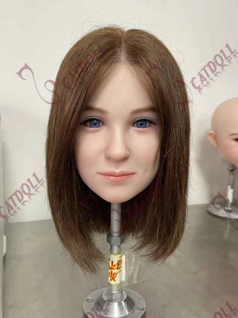
CATDOLL Airi Soft Silicone Head

You can choose the skin tone, eye color, and wig, or upgrade to implanted hair. Soft silicone heads come with a functio...

Articles 2026-02-22