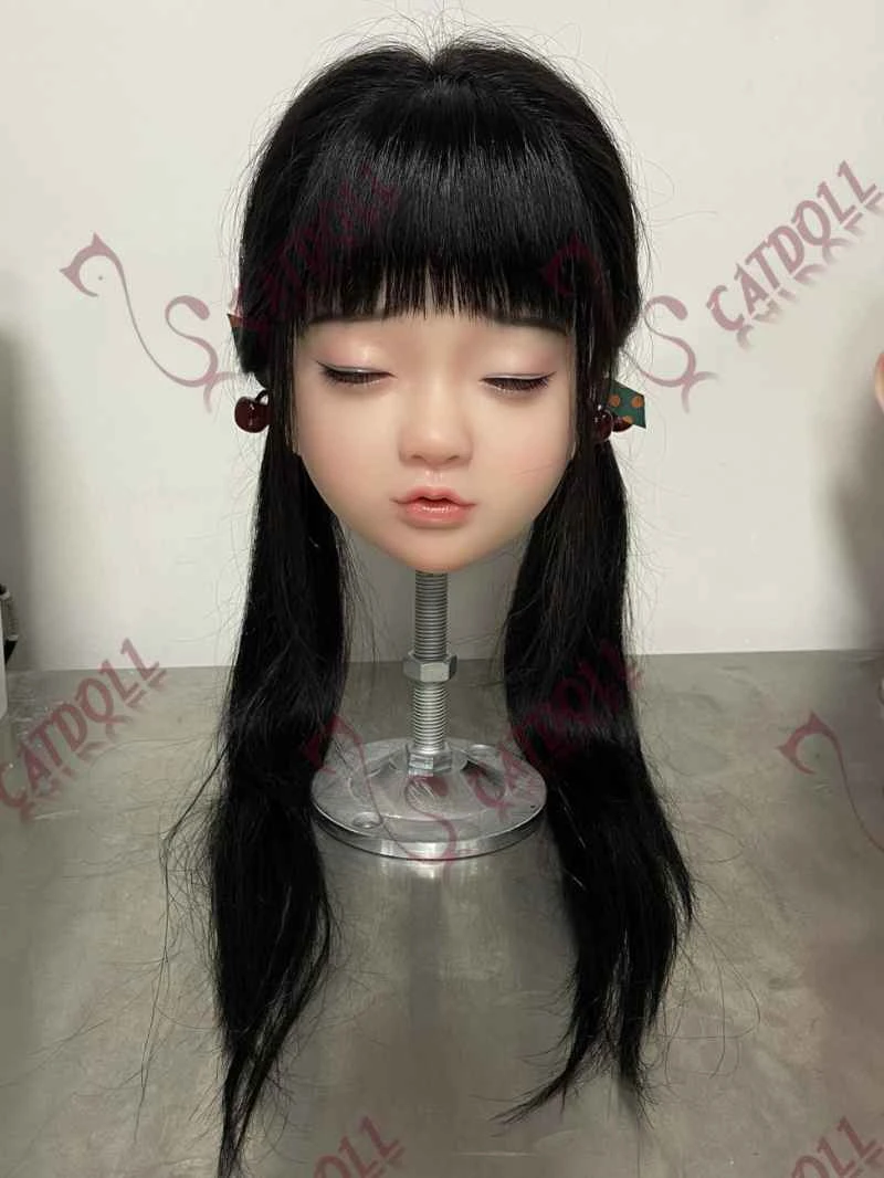
Gas state monitoring system based on intelligent sensor NPX
2026-04-06 07:28:50··#1
Abstract : This paper introduces the design and implementation of a high-precision gas state monitoring system based on Cygnal's C8051F330 microcontroller and GE Nova Sensor's NPX digital sensor. The paper focuses on the core chip, hardware structure, and numerical analysis method for accurately calculating SF6 gas density. Keywords : NPX, C8051F330, SF6 gas state monitoring system, numerical algorithm. The concept of unmanned operation in power plants and substations in power systems has been proposed for a long time. Microcontroller technology has enabled the widespread application of online monitoring in various aspects of power systems, providing technical support for unmanned operation. Through bus communication technology, staff can use background service programs in the office to monitor, detect, and perform fault maintenance on power equipment operating in the field. Sulfur hexafluoride (SF6) is widely used in high-voltage, high-capacity, and high-parameter electrical equipment due to its excellent electrical properties and stable chemical structure. With the development of power systems towards larger capacity and higher parameters, SF6 high-voltage circuit breakers have been widely used in power generation and supply enterprises. The normality of the state parameters of SF6 insulating gas seriously affects the working performance of the circuit breaker. With the increasing number of SF6 high-voltage electrical appliances and the widespread application of SF6 enclosed combined electrical systems, how to correctly conduct SF6 gas density monitoring is an urgent problem to be solved. To meet the various performance requirements of SF6 circuit breakers, a monitoring sub-unit was designed, using the Cygnal C8051F330 microcontroller as its core and the GENova Sensor's latest tire pressure monitoring system dedicated chip NPX as the sensor chip. This sub-unit measures and calculates three state parameters of SF6 insulating gas: pressure, temperature, and density. The monitoring system is composed of a PC and multiple monitoring sub-units, connected via an RS485 bus. The PC's background service program queries and controls the sub-unit status. 1. Overall Design of the Monitoring Sub-unit The overall design of the monitoring sub-unit consists of four parts: a sensor module, a main control module, an LED display and relay control module, and a RS485 bus transmission module. Since the sensor needs to be encapsulated inside the SF6 circuit breaker, the sensor section and the other three sections are designed on two separate printed circuit boards, transmitting data via connecting lines. The overall structure is shown in Figure 1. The sensor module's functions are performed independently by a single NPX chip, which integrates a microprocessor and pressure/temperature sensors, making it powerful. The NPX measures, compensates for, and calibrates the pressure and density of SF6 gas, quantizing it into digital signals and transmitting them to the MCU of the main control module. After receiving the data from the NPX, the main control module processes and analyzes the data, then outputs and displays it, and controls the relay status and status indicator lights based on the analysis results. Simultaneously, the main control module is connected to a MAX485 bus via an optocoupler, allowing for data transmission through the 485 bus and querying and controlling the monitoring slave unit using a PC's background service program. The sensor module and the main control module are the core components of the entire system; their design will be analyzed in detail below. 2. NPX Chip Introduction In the sensor module, the NPX chip is used as the pressure and temperature sensor. The NPX-1 is a second-generation TPMS (Tire Pressure Monitoring System) pressure sensor launched by GE Nova Sensor in early 2004. It integrates an 8-bit RISC microprocessor (using Philips' CPUPCH7970), a pressure sensor, a temperature sensor, a voltage sensor, a low-noise amplifier, and a 12-bit A/D converter; a built-in RC oscillator provides the system clock, eliminating the need for an external crystal oscillator. Its silicon piezoresistive pressure sensor uses a Wheatstone bridge composed of high-precision semiconductor resistance strain gauges as the force-to-electricity conversion measurement circuit, offering high measurement accuracy and low power consumption. The internal block diagram of the NPX-1 chip is shown in Figure 2. The functions of the main pins of the NPX are listed in Table 1. The NPX contains the measurement, compensation, and calibration procedures for the pressure sensor. During production, each NPX chip is processed by the factory, collecting 12 sets of data at different temperature points (25℃ and 75℃), different pressure points (0%, 50%, and 100% of full scale), and different battery voltage points (2.3V and 3.1V). The data is then calculated using GE NovaSensor's proprietary calibration formula, and the compensation and calibration parameters are stored in the NPX's E2PROM. During measurement, the fixed pressure compensation calibration program automatically calculates the measured data to obtain an accurate measurement value. Simultaneously, the NPX chip can operate in extreme environments, such as high temperatures (above 100℃), low temperatures (-40℃), water vapor (low-temperature condensation and freezing; the NPX sensor has a unique anti-condensation and anti-freezing function), vibration, and shock. Furthermore, after each pressure measurement, the NPX uses built-in code to check the sensor's health status to ensure the reliability of the measurement results. The NPX embodies a perfect combination of traditional pressure sensors and microprocessor digital circuits, possessing unique advantages suitable for TPMS applications and also applicable to other types of engineering applications. In the design of the SF6 gas state monitoring system, the NPX, with its unique and excellent performance, met the design requirements. 3 Main Control Module and its Interface with NPX 3.1 Main Control Module The main control module consists of a Cygnal C8051F330 microcontroller and a power control circuit. The C8051F330 is a mixed-signal SoC-type 8-bit microcontroller launched by Cygnal Corporation of the United States; it is a highly integrated mixed-signal system-on-a-chip. The C8051F330, equipped with on-chip power-on reset, VDD monitor, watchdog timer, and clock oscillator, is a truly independent system-on-a-chip (SoC). Its Flash memory also features in-system reprogramming capability, allowing for non-volatile data storage and field updates of the 8051 firmware. User software has complete control over all peripherals and can shut down any or all peripherals to save power. 3.2 Interface Design between the Main Control Module and NPX Both the C8051F330 and NPX's general-purpose I/O ports operate at 3.3V, thus data transmission can be directly achieved using I/O. The design utilizes three pairs of I/O ports to complete the communication between the C8051F330 and the NPX, and its interface circuit is shown in Figure 3. The communication process between NPX and C8051F330 is as follows: NPX's P11 pin serves as global synchronization and is high when there is no data transmission. Before transmitting data, it sends a falling edge to C8051F330's P0.7 pin, triggering C8051F330's external interrupt 1, thus enabling the microcontroller to execute an interrupt handler to receive data from NPX. NPX's P14 pin serves as bit synchronization, and P15 pin serves as the data transmission end. When a falling edge is received from the bit synchronization pin, the microcontroller reads one bit of data from the data end. NPX collects data every 2 seconds and sends it to the main control module. Temperature and pressure are each 8 bits, plus 1 bit of NPX status flag, for a total of 17 bits of data to be transmitted. The timing of the entire communication process is shown in Figure 4. The I/O ports for communication between C8051F330 and NPX need to be configured as follows: After C8051F330's P0.7 pin receives a falling edge sent by NPX, it jumps to the interrupt subroutine of external interrupt 1. In the interrupt subroutine, Timer 0 is started, and a variable `unsigned char bit_cntr` is defined to calculate the number of bits of data to be read. When a falling edge is received at pin P1.0, the microcontroller reads 1 bit of data from pin P1.1, and `bit_cntr` is incremented by 1. When the value of `bit_cntr` is 17, it indicates that the data reception is complete. The `Data_Flag` flag is set to notify the main program that data has been received, and Timer 0 is turned off, exiting the interrupt subroutine. If NPX encounters an error while sending data, less than 17 bits of data will be transmitted. In this case, Timer 0 will overflow. After the program detects the Timer 0 overflow, it will clear the `Data_Flag` flag and exit the interrupt subroutine. 4 System Data Processing After receiving the data from NPX, the system needs to process it. Based on the received temperature and pressure data, it calculates and determines whether there is a leak of SF6 gas. In practical engineering applications, the standard SF6 gas pressure at 20°C is generally given as a reference standard. Therefore, the main control module must convert the received data into the pressure at 20°C. There are generally three methods for processing data: ① Using a lookup table. Some manufacturers provide tables showing the relationship between SF6 gas pressure and temperature for users to consult, which seems more convenient; however, for temperature and pressure values not listed in the table, interpolation is required. Obviously, using a pre-defined table to determine the pressure at different temperatures also has some error, but it is still sufficient for engineering requirements. The biggest drawback of this method is that it requires a large amount of storage space to store the pressure and temperature table data. ② Treating it as an ideal gas and calculating the pressure-temperature coefficient. For reference, treating it as an ideal gas, the equation of state PV=RT can be used. For example, for a high-voltage SF6 circuit breaker with a rated pressure of 0.7MPa (absolute pressure) at 20℃, the following formula is given: P=0.7T/(273+20). Since SF6 is a non-ideal gas in actual engineering applications, the result obtained by this method has a relatively large error. The higher the rated pressure of the gas, the greater the error in the pressure-temperature coefficient obtained after idealization. ③ Processing the data using empirical formulas. To calculate the state parameters of SF6 gas more accurately, some empirical formulas are available. A typical example is the Beattie-Bridgman empirical formula: Among all the processing methods, the Beattie-Bridgman formula is the closest to the actual value and has the smallest error. Therefore, it is used for data processing. The equations for P, T, and C are constructed as follows: From equations (1) and (2), it can be seen that after determining the pressure P and temperature T, the density C of SF6 gas at this time can be obtained by solving a cubic equation. Since it is a cubic equation, the Newton-Raphson method is used to solve it in the programming calculation to ensure that the truncation error is minimized. After calculating the density of SF6 gas, let T = 20 + 273, and then calculate the pressure P20 of SF6 gas at 20℃ using equation (1). (Software implementation program omitted - editor's note) The unit of pressure P in the program is kPa. The main control module determines whether a gas leak has occurred based on the converted pressure of the current gas at 20°C and a given standard value, and then controls the status of relays and status indicator lights according to the determination result. Conclusion Practical testing shows that the SF6 gas status monitoring system can accurately sample and process pressure and temperature signals. In particular, the use of a high-performance numerical analysis algorithm—Newton's iteration method—achieves high-precision density calculation, effectively, stably, and reliably ensuring the accuracy of the monitoring data. Furthermore, the NPX chip used in this system represents a perfect combination of traditional pressure sensors and microprocessor digital circuits. Its convenient interface with the CygnalMCU makes it widely applicable.