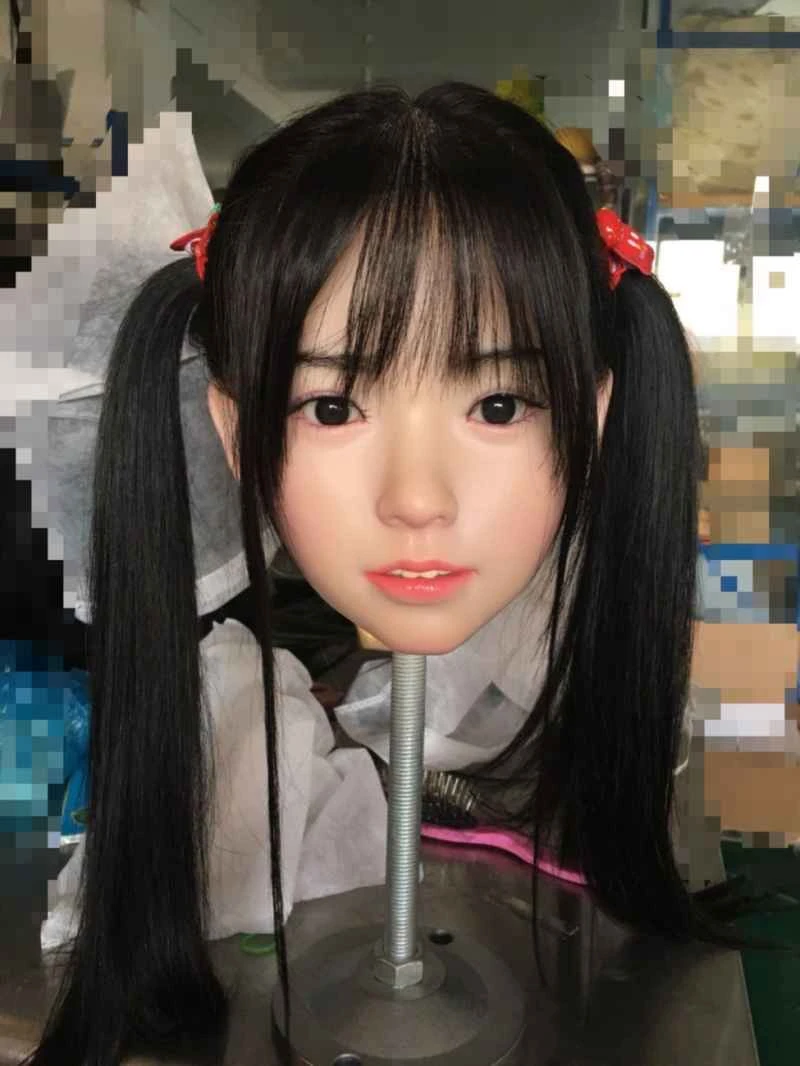
Application of frequency conversion system in short fiber spinning equipment
2026-04-06 04:48:24··#1
1. Introduction Short fiber products, such as polyester hollow fiber, trilobal fiber, seven-hole hollow fiber, ten-hole hollow fiber, as well as various flame-retardant fibers, antibacterial fibers, and silicone-reinforced fibers (PP cotton), are characterized by good hand feel, elasticity, and high loft. These products are suitable for producing spray-bonded cotton, non-woven fabrics, needle-punched fabrics, clothing, toys, pillow fillings, quilts, artificial fur, etc. Due to the strong sales of these products in domestic and international markets, many companies are upgrading their existing production lines or introducing new production equipment. This article presents a mature frequency conversion technology solution for this series of equipment. Short fiber equipment includes two main types: pre-spinning and post-spinning equipment. The post-spinning equipment and processes include: bundling—drawing and oiling—cracking—heat setting—cutting—packaging—inspection—finished product—shipping. The most important process is from drawing to crimping, which involves four transmission mechanisms (first drawing, second drawing, third drawing, and crimping). In traditional processes, a large motor controls all four transmissions via mechanical gears on a single shaft. As the weaknesses of single-shaft transmission gradually become apparent, such as high gearbox damage rate, difficulty in adjusting draft ratio, and easy breakage of single shaft, most imported chemical fiber spinning equipment currently uses independent frequency conversion transmission. When using independent frequency conversion transmission, two crucial issues must be addressed: (1) the problem of power generation and energy feedback; and (2) the problem of synchronous drafting. Both are due to the needs of chemical fiber spinning process. An important task of spinning is to make the fiber filaments achieve the process requirements through different drafting speeds, which leads to the first and second drafting stages often being in a power generation state. At the same time, it is necessary to ensure that the four independent transmissions accelerate proportionally during acceleration, deceleration, and constant speed, which leads to the problem of synchronous drafting. 2 Construction of Multi-Motor Transmission System In the four independent transmission rollers of chemical fiber spinning, in order to maintain a certain draft ratio, the first and second drafting stages are usually in a power generation state, while the third drafting and crimping stages are in an electric state. 2.1 Electric and power generation are usually the two operating states of the frequency converter speed regulation system, namely electric and power generation. In a variable frequency speed control system, motor deceleration and shutdown are achieved by gradually reducing the frequency. At the instant the frequency decreases, the synchronous speed of the motor drops accordingly, while the rotor speed remains unchanged due to mechanical inertia. When the synchronous speed w1 is less than the rotor speed w, the phase of the rotor current changes by almost 180 degrees, and the motor switches from motoring to generating mode. Simultaneously, the torque on the motor shaft becomes braking torque Te, causing the motor speed to drop rapidly, and the motor enters a regenerative braking state. The regenerated electrical energy P is fed back to the DC circuit after full-wave rectification by the freewheeling diode. Since the electrical energy in the DC circuit cannot be fed back to the grid through the rectifier bridge, it is absorbed only by the inverter's own capacitor. Although other parts can consume electrical energy, the capacitor still accumulates charge for a short period, forming a "pumped voltage," causing the DC voltage Ud to rise. Excessively high DC voltage will damage various components. How should the regenerated electrical energy be handled? The simplest method is regenerative braking, which involves adding a discharge resistor unit to the DC side of the frequency converter to dissipate regenerated electrical energy through a power resistor for braking. However, since the first and second traction drives are always in a generating state, their power output is considerable, requiring a large braking resistor array in actual operation. Therefore, how to utilize this electrical energy is an urgent problem to be solved. 2.2 Construction of Multi-Motor Drive Control For motors that frequently start and brake, or operate in four quadrants, how to handle the braking process not only affects the dynamic response of the system but also raises economic concerns. Thus, regenerative braking has become a focus of discussion. However, most general-purpose frequency converters currently cannot achieve regenerative energy through a single frequency converter. To solve this problem, this paper introduces a regenerative energy feedback system with a shared DC bus. In this way, the regenerative energy generated by braking can be fully utilized, thereby achieving both energy saving and regenerative energy processing. The multi-drive control circuit includes a DC input circuit, a DC bus power supply circuit, and several inverters (or general-purpose frequency converters with input phase loss protection). The energy required by the motor is output in DC mode through the PWM inverter. In the multi-drive mode, the induced energy during braking is fed back to the DC circuit. Through the DC circuit, this feedback energy can be consumed by other motors in the motoring state. When the braking requirements are particularly high, only a common braking unit needs to be connected in parallel on the common bus. The wiring in Figure 2 is a typical braking method with a common DC bus. According to the characteristics of the chemical fiber spinning equipment, the first drafting M1 and the second drafting M2 are in the generating state during normal operation, while the third drafting M3 and the crimping M4 are in the motoring state. Since the generation of M1 and M2 is caused by the motoring of the third drafting, the feedback energy generated by these two motors is sufficient to consume the motored M3 and M4 without causing an increase in the DC circuit bus voltage. This completely solves the problem of regenerative energy braking, thus keeping the system in a relatively stable state. 2.3 DC Input Circuit The DC input circuit provides DC power to the multi-motor drive system, and its main component is the rectifier. However, we know that when the AC/DC power supply starts, a starting current as high as 50 times the system's nominal current is generated, charging the input capacitors (mainly referring to the electrolytic capacitors of the VF1-VF4 frequency converters). This starting current causes a voltage drop on the main power supply, affecting the normal operation of other devices connected to the same power network, and may even blow the input line fuse. Typically, the front end of the offline power supply consists of a bridge rectifier and a large-capacity filter capacitor. During startup, charging the large-capacity filter capacitor generates a surge current at the input terminal, known as the starting current. If this starting current is not limited, the input fuse may blow or trigger the circuit breaker. Therefore, the core issue of the DC input circuit is controlling the starting current. One solution is to connect the impedance in parallel with a silicon-based circuit breaker or electromechanical relay, and then in series with the rectifier. This significantly reduces the inrush current, ensuring the reliability of the DC input circuit. 2.4 Characteristics of Multi-Motor Drives The multi-motor drive control method using a shared DC bus in the chemical fiber post-spinning equipment has the following significant characteristics: a. The shared DC bus and shared braking unit greatly reduce the redundant configuration of rectifiers and braking units, resulting in a simple, reasonable, economical, and reliable structure. b. The intermediate DC voltage of the shared DC bus is constant, and the parallel capacitors provide large energy storage capacity. c. Each motor operates under different conditions, with complementary energy feedback, optimizing the dynamic characteristics of the system. d. It improves the system power factor, reduces grid harmonic current, and improves system power efficiency. 3 Control of Multi-Motor Drive Drafting Synchronization In the four-stage drive (three drafting and crimping) of the chemical fiber post-spinning equipment, the draft ratio must be determined based on the speed synchronization of the four drive motors. Typically, there is a main setpoint signal. The goal of synchronization control is to evenly distribute this signal to the four frequency converters (M1, M2, M3, and M4) according to the draft ratio requirements, ensuring that the four drives maintain proportional synchronization during acceleration, constant speed, and deceleration. The following mainly discusses three commonly used synchronization control schemes. 3.1 Analog Synchronous Control When each transmission unit in a machine or production line is driven by an independent frequency converter, a synchronous controller is needed to ensure that all units work synchronously and in coordination under a single master speed setting (here, a fixed draw ratio). This synchronous controller can individually adjust the transmission speed of each unit to achieve synchronous operation of each unit at a certain proportional speed. The total master setting voltage (determined by a potentiometer) is output through a given integrator, enabling soft start and soft stop. This synchronous controller can output multiple analog signals to the frequency converter (here, VF1-VF4). The analog input setting method is a high-precision control method, generally achieving a resolution of "11 bits + sign" for voltage or "10 bits" for current. 3.2 Pulse Signal Synchronous Control In electronics, a pulse signal is a continuous pulse signal emitted at a certain voltage amplitude and time interval. The time interval between the first and second pulses is called the period; and the number of pulses generated per unit time (e.g., 1 second) is called the frequency. Normally, the maximum input pulse frequency can be selected between 0.1KHz and 50KHz. Under the control of the master potentiometer, the VF1 inverter outputs the number of synchronous pulses to VF2. VF2 receives the number of pulses and operates while simultaneously outputting the number of synchronous pulses to VF3, and so on until VF4. Due to the strong anti-interference ability of the digital processing technology of pulse signals, it is also widely used in synchronous control. 3.3 Communication bus synchronous control Setting the frequency through the network is a high-precision frequency setting method. It has the advantages of high communication speed, stability and reliability, and simple wiring. Moreover, in analog control, the output end passes through a digital-to-analog converter, then through wires, and then through an analog-to-digital converter to enter the input end (inverter) before it can participate in the control. The difference in the number of bits of the two converters and the loss of wires may cause certain errors. However, the communication transmission is a direct digital quantity that does not need to be converted, so there is no error. It will not cause loss during transmission, and the response speed will also be very high. Normally, synchronous control can adopt the asynchronous communication control method of RS485 bus, as shown in Figure (3). Using a frequency converter with a built-in RS485 interface facilitates communication with a host computer. It can also be connected to a fieldbus or local area network for information exchange. Common network and bus types include PROFIBUS, Modbus, and FF, but a dedicated interface card is required. 4. Conclusion The application of frequency converter technology in chemical fiber post-spinning equipment should be tailored to the specific requirements of the process. Selecting a multi-motor drive control structure with a shared DC bus can effectively solve the continuous power generation problem in the first and second stages, while synchronous control achieves a constant draft ratio. This solution has been successfully applied in the technical upgrades of several short fiber post-spinning equipment systems.