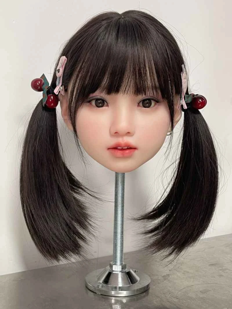
Abstract: This article introduces five cases of inverter fault handling based on the author's personal experience in repairing inverters. Keywords : Inverter maintenance 1 Introduction Based on the author's long-term experience in repairing inverters, five cases of inverter fault handling are introduced. [b]2 Five cases of inverter fault handling (1) Inverter drive motor vibration[/b] When repairing a Yaskawa 6l6PC5-5.5kW inverter, the customer reported that the motor was vibrating. The first reaction was that the output voltage was unbalanced. After checking the power devices, no damage was found. The inverter was powered on and the display was normal. The inverter was run and the three-phase output voltage was indeed unbalanced. The waveform of the six digital outputs was tested and the lower bridge waveform of the W phase was found to be abnormal. The resistor, diode and optocoupler of the W phase were measured in turn. It was found that the diode providing reverse voltage was broken down. After replacement, the inverter was powered on and the three-phase output voltage was balanced. The problem was solved. (2) Inverter Frequency Cannot Reach High Frequency When repairing a Puchuan 220V, single-phase, 1.5kW inverter, the customer indicated that the frequency could not reach high enough, only 20Hz. The first thought was that the parameters might be incorrect. Checking the parameters, the highest and upper limit frequencies were both 60Hz, indicating it wasn't a parameter issue. The next suspicion was an incorrect frequency setting method. After changing the frequency setting to the panel, the inverter could run up to 60Hz. Therefore, the problem was pointed to the analog input circuit. Checking this circuit revealed a damaged surface-mount capacitor. After replacing it, the inverter functioned normally. (3) Inverter Overcurrent When repairing a Taian N2 series, 400V, 3.7kW inverter, the customer indicated that it displayed an overcurrent during startup. After confirming the module was intact, the inverter was powered on. Without the motor running, it displayed OC2 momentarily upon startup. The first thought was a damaged current detection circuit. Replacing the detection circuit did not eliminate the fault. Therefore, the testing scope was expanded to check the drive circuit. During the inspection of the drive waveform, an abnormal waveform was found in one path. Upon checking the surrounding components, a short-circuited surface-mount capacitor was discovered. After replacement, the inverter operated normally. [b][align=center]For details, please click: Inverter Repair Case Analysis[/align][/b]