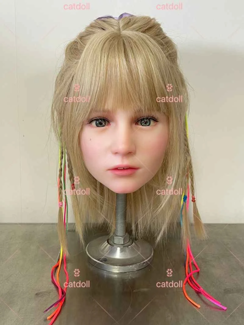
Several methods for setting the frequency of a frequency converter
2026-04-06 03:12:09··#1
Inverter frequency converters (INCRs) are a relatively new and energy-saving product that has emerged in recent years. They represent a perfect combination of power electronics and computer application technologies. Due to their high speed control accuracy, ease of operation, and energy savings (when the output frequency is less than 50Hz), they are now widely used in machinery, chemical, metallurgical, and light industries. Depending on the specific application, there are different methods for setting the frequency of an INCR. Taking the Mitsubishi FR-500 series INCR as an example, we will explain the characteristics of several frequency setting methods. INCR frequency setting methods can be divided into two main categories: the first is using the INCR operation panel, and the second is using the INCR control terminals. The first method, using the INCR operation panel, only requires the up and down keys on the panel to set the frequency. This method does not require external wiring, is simple, has high frequency setting accuracy, and is a digital frequency setting method suitable for setting the frequency of a single INCR. The second method, using the INCR control terminals, has two sub-methods: the first uses an external potentiometer, and the second utilizes the special function of the INCR control terminals to set the frequency using an electric potentiometer. The first method uses an external potentiometer for frequency setting. As shown in Figure 1, terminal 10 of the FR-500 series inverter provides a standard 10V DC voltage, terminal 2 is the frequency setting input terminal, and terminal 5 is the common terminal for analog input. By adjusting the output voltage of terminal 2 of the external potentiometer R, the input voltage value of terminal 2 of the inverter is changed, which in turn changes the frequency setting value of the inverter, thus achieving the purpose of frequency setting. This method has the following advantages: (1) Simple wiring: just connect the three terminals of the potentiometer to the voltage input terminal, voltage output terminal, and common terminal of the inverter. (2) Simple frequency setting and convenient operation: just turn the knob of the external potentiometer to set the frequency. (3) Flexible installation: the external potentiometer can be installed in any position according to actual needs for remote operation. However, this method also has the following disadvantages: (1) Temperature drift: because the resistance value is affected by temperature, when the external temperature changes, the resistance value also changes, and the frequency setting value also changes. (2) Low anti-interference ability. When there is strong electromagnetic interference in the surroundings, an induced voltage will be generated in the connecting cable between the inverter and the external potentiometer, causing the voltage value input to terminal 2 of the inverter to change, which in turn causes the frequency setting value to change and affects the stability of the set frequency. (3) The installation distance of the potentiometer is limited. Theoretically, the voltage variation range of terminal 2 of the inverter is 0-10V, but if the installation distance of the external potentiometer is too far, the connecting cable will generate a voltage drop, and the voltage at terminal 2 of the inverter will not reach 10V, thus causing the output frequency to not reach the highest setting value. Therefore, this inverter frequency setting method is generally used in situations with low speed regulation accuracy, low surrounding interference, and small changes in ambient temperature, and belongs to analog quantity regulation. The second method utilizes the specific functions of the inverter control terminals. By setting the internal parameters of the inverter, terminals RH and RM can be made into electric potentiometers. That is, when RH is connected to the common terminal SD, the inverter output frequency increases; when RM is connected to SD, the inverter output frequency decreases, thus achieving the purpose of frequency setting, as shown in Figure 2. Compared with the first method, this method has the following advantages: (1) High frequency setting accuracy. The external potentiometer method is an analog setting method, and the frequency change range is within ±0.2% of the maximum output frequency. However, when using an electric potentiometer to set the frequency, the frequency change range is within 0.01% of the maximum output frequency. (2) Strong anti-interference ability. Since it is only a switch signal input, it is not affected by the surrounding electromagnetic field. (3) No temperature drift. Since the external potentiometer is eliminated, it is not affected by changes in ambient temperature. (4) Flexible installation. Buttons SB1 and SB2 can be installed in any position. (5) Good synchronization performance. It can simultaneously realize the frequency increase and decrease of multiple inverters. In conclusion, we should choose the appropriate frequency setting method according to actual needs in order to achieve the desired application effect.