Read next
CATDOLL 66cm Baby Boy Silicone Doll – Lifelike Newborn Style
Height: 66cm Male Silicone Weight: 8.8kg Shoulder Width: 21cm Bust/Waist/Hip: 44/44/47cm Oral Depth: N/A Vaginal Depth:...
Articles
2026-02-22
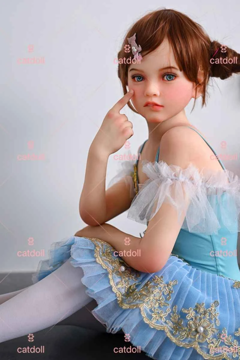
CATDOLL 123CM Milana TPE
Articles
2026-02-22

CATDOLL CATDOLL 115CM Nanako Silicone Doll
Articles
2026-02-22
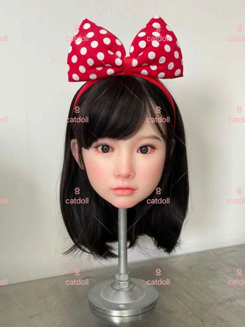
CATDOLL Yuki Soft Silicone Head
Articles
2026-02-22