Read next
A Brief Discussion on Artistic Design in Human-Computer Interface Design
[Abstract] With people's higher pursuit of life and the development of ergonomics, art design is increasingly valued...
Articles
2026-02-22
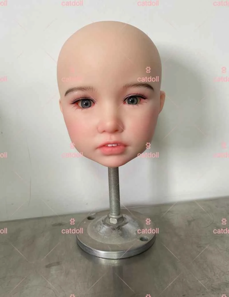
CATDOLL Coco Soft Silicone Head
Articles
2026-02-22
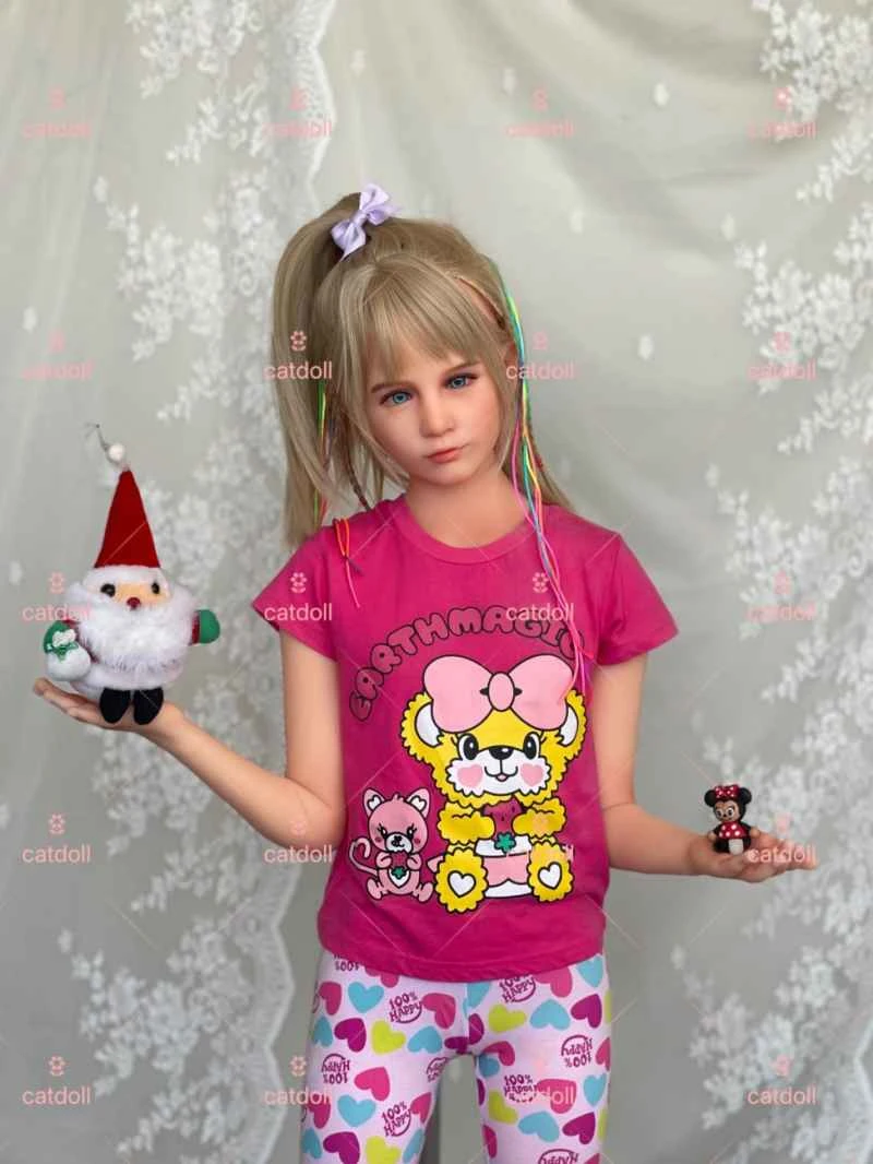
CATDOLL 123CM Olivia TPE
Articles
2026-02-22
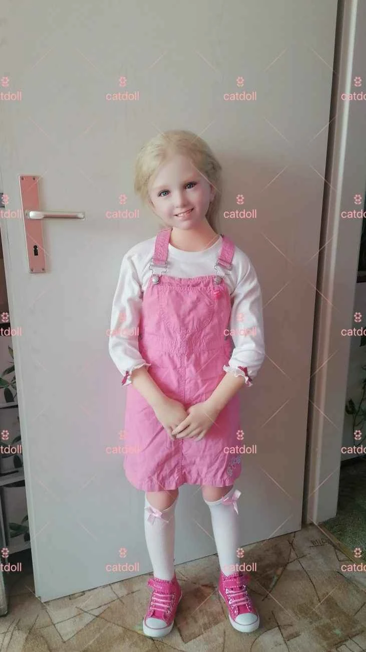
CATDOLL 123CM Maria (TPE Body with Hard Silicone Head)
Articles
2026-02-22