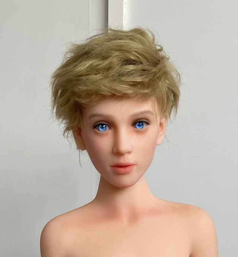
1 Overview In automatic production lines for modular machine tools, three types of slides are generally set according to different machining accuracy requirements: (1) hydraulic slides, used in roughing operations with large cutting volume and low machining accuracy requirements; (2) mechanical slides, used in semi-finishing operations with medium cutting volume and certain machining accuracy requirements; (3) CNC slides, used in finishing operations with small cutting volume and high machining accuracy requirements. Programmable logic controllers (PLCs) are widely used in industrial automatic control due to their advantages such as strong versatility, high reliability, simple instruction system, easy programming and learning, easy to master, small size, less maintenance work, and convenient on-site interface installation. In particular, they have shown excellent performance in the control of automatic production lines for modular machine tools and the S, T, M function control of CNC machine tools. The open-loop servo mechanism of stepper motor controlled by PLC is applied to the control of CNC slides on automatic production lines for modular machine tools. This can eliminate the need for the CNC system of this unit, reducing the cost of the control system of this unit by 70-90%, or even only occupying 3-5 I/O interfaces and <1KB of memory of the PLC control unit. Especially in large-scale automated lines, the cost of the control system can be significantly reduced. 2. Structure of CNC Slide Table Controlled by PLC Generally, the CNC slide table in a combined machine tool automated line adopts an open-loop servo mechanism driven by a stepper motor. A CNC slide table controlled by a PLC consists of a programmable controller, a loop pulse distributor, a stepper motor driver, a stepper motor, and a servo transmission mechanism. Gears Z1 and Z2 in the servo transmission mechanism should be designed with backlash elimination measures to avoid reverse dead zones or reduced machining accuracy; the choice of ball screw pairs should be determined based on the machining accuracy requirements of the unit. Using ball screw pairs has advantages such as high transmission efficiency, good system rigidity, high transmission accuracy, and long service life, but the cost is higher and it cannot self-lock. 3. PLC Control Method for CNC Slide Tables The control factors of CNC slide tables are mainly three: 3.1 Stroke Control The stroke control of general hydraulic and mechanical slide tables is achieved using position or pressure sensors (limit switches/dead stops); while the stroke of CNC slide tables is achieved using digital control. As can be seen from the structure of the CNC slide, the stroke of the slide is proportional to the total rotation angle of the stepper motor. Therefore, it is only necessary to control the total rotation angle of the stepper motor. As can be seen from the working principle and characteristics of the stepper motor, the total rotation angle of the stepper motor is proportional to the number of input control pulses. Therefore, the number of pulses output by the PLC can be determined according to the displacement of the servo mechanism: n = DL/d (1) Where DL is the displacement of the servo mechanism (mm) d is the pulse equivalent of the servo mechanism (mm/pulse) 3.2 Feed speed control The feed speed of the servo mechanism depends on the speed of the stepper motor, and the speed of the stepper motor depends on the input pulse frequency. Therefore, the pulse frequency output by the PLC can be determined according to the feed speed required by the process: f = Vf/60d (Hz) (2) Where Vf is the feed speed of the servo mechanism (mm/min) 3.3 Feed direction control Feed direction control is the direction control of the stepper motor. The direction of rotation of a stepper motor can be changed by altering the energizing sequence of its windings. For example, a three-phase stepper motor rotates forward when energized in the sequence A-AB-B-BC-C-CA-A…; it rotates in reverse when energized in the sequence A-AC-C-CB-B-BA-A… Therefore, this can be achieved by changing the output sequence of the hardware ring distributor using the direction control signal output from the PLC, or by changing the sequence of output pulses through programming to alter the energizing sequence of the stepper motor windings. 4. PLC Software Control Logic As can be seen from the PLC control method for the slide, the total number of input pulses and the pulse frequency of the stepper motor should be controlled accordingly. Therefore, a pulse signal generator with controllable total number of pulses and pulse frequency is set up in the control software. For control pulses with lower frequencies, a timer in the PLC can be used, as shown in Figure 2. The pulse frequency can be controlled by the timing constant of the timer, and the total number of pulses can be controlled by setting a pulse counter C10. When the number of pulses reaches the set value, the counter C10 activates, cutting off the pulse generator circuit and stopping its operation. When there is no pulse input, the stepper motor of the servo mechanism stops operating, and the servo actuator is positioned. When the displacement speed requirement of the servo actuator is high, a high-speed pulse generator in the PLC can be used. Different PLCs can have high-speed pulse frequencies of 4000-6000Hz. For general servo mechanisms on automatic lines, the speed requirement can be fully met. 5 Servo Control, Drive and Interface 5.1 Composition of Stepper Motor Control System The stepper motor control system consists of a programmable controller, a loop pulse distributor and a stepper motor power driver. In the control system, the PLC is used to generate control pulses; a certain number of square wave pulses are output through PLC programming to control the rotation angle of the stepper motor and thus control the feed amount of the servo mechanism; at the same time, the pulse frequency—that is, the feed speed of the servo mechanism—is controlled through programming; the loop pulse distributor distributes the control pulses output by the programmable controller to the corresponding windings according to the stepper motor energization sequence. The stepper motor controlled by the PLC can use a software loop distributor or a hardware loop distributor as shown in Figure 1. Using soft ring circuits consumes more PLC resources, especially when the number of phases in the stepper motor windings (M>4). This should be fully considered for large production lines. While using a hardware ring distributor is slightly more complex, it saves on the number of PLC I/O ports. Several dedicated chips are available on the market. The stepper motor power driver amplifies the control pulses output by the PLC to tens to hundreds of volts and a few to tens of amps. Generally, PLC output interfaces have a certain driving capability, while typical transistor DC output interfaces only have a load capacity of tens to hundreds of volts and tens to hundreds of milliamps. However, power stepper motors require tens to hundreds of volts and a few to tens of amps, therefore, a driver should be used to amplify the output pulses. 5.2 Programmable Controller Interface: If a hardware ring distributor is used for the servo mechanism, the number of PLC I/O ports required is less than 5, typically only 3. One I/O port is used as the start control signal; two O ports are used: one as the PLC's pulse output interface, connected to the clock pulse input terminal of the servo system's hard loop, and the other as the stepper motor's direction control signal, connected to the phase sequence distribution control terminal of the hard loop, as shown in Figure 3; the servo system uses a software loop distributor. 6. Application Examples and Conclusions The PLC-controlled open-loop servo mechanism was used in the CNC slides of a large production line. Each slide only occupies 4 I/O interfaces, saving space in the CNC control system. Its pulse equivalent is 0.01~0.05mm, and the feed speed is Vf=3~15m/min, fully meeting the process requirements and machining accuracy requirements.