Read next
CATDOLL 146CM Vivian TPE
Height: 146cm A-cup Weight: 26kg Shoulder Width: 32cm Bust/Waist/Hip: 64/54/74cm Oral Depth: 3-5cm Vaginal Depth: 3-15c...
Articles
2026-02-22

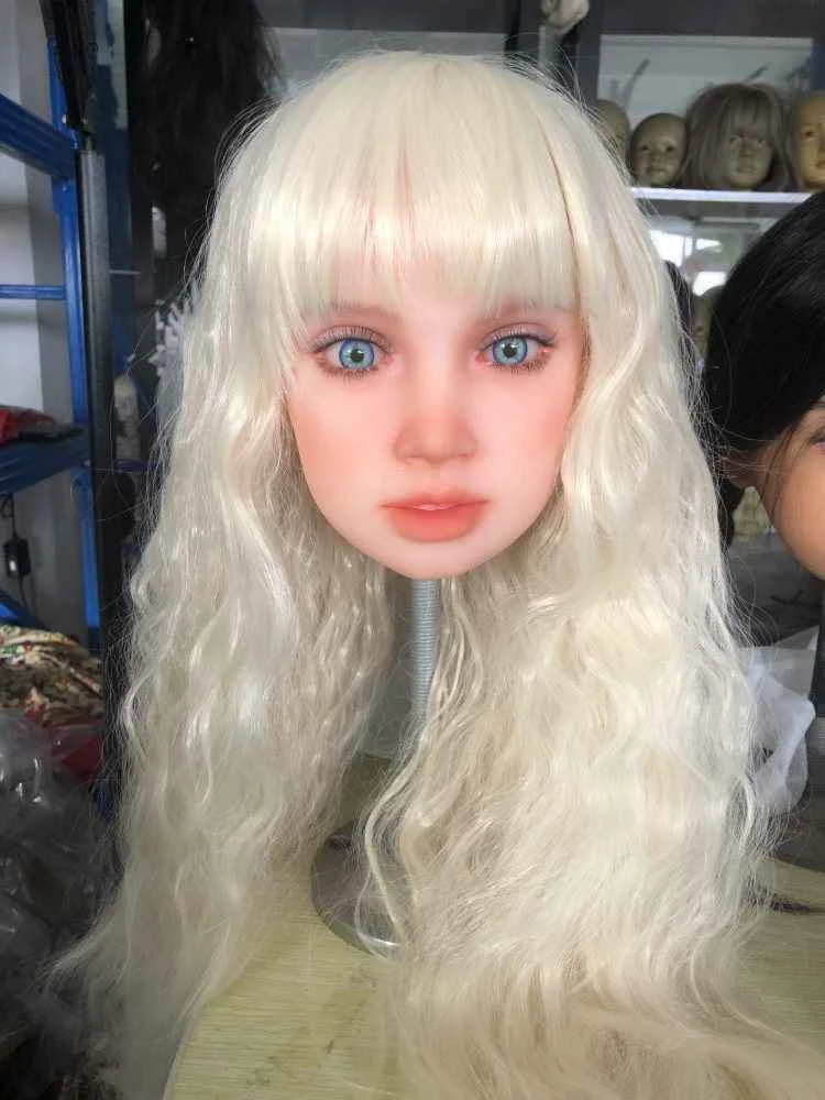
CATDOLL 146CM Ya TPE (Customer Photos)
Articles
2026-02-22

Analysis: Latest Developments in Automotive Drive Belt Technology
Articles
2026-02-22
CATDOLL 128CM Luisa
Articles
2026-02-22