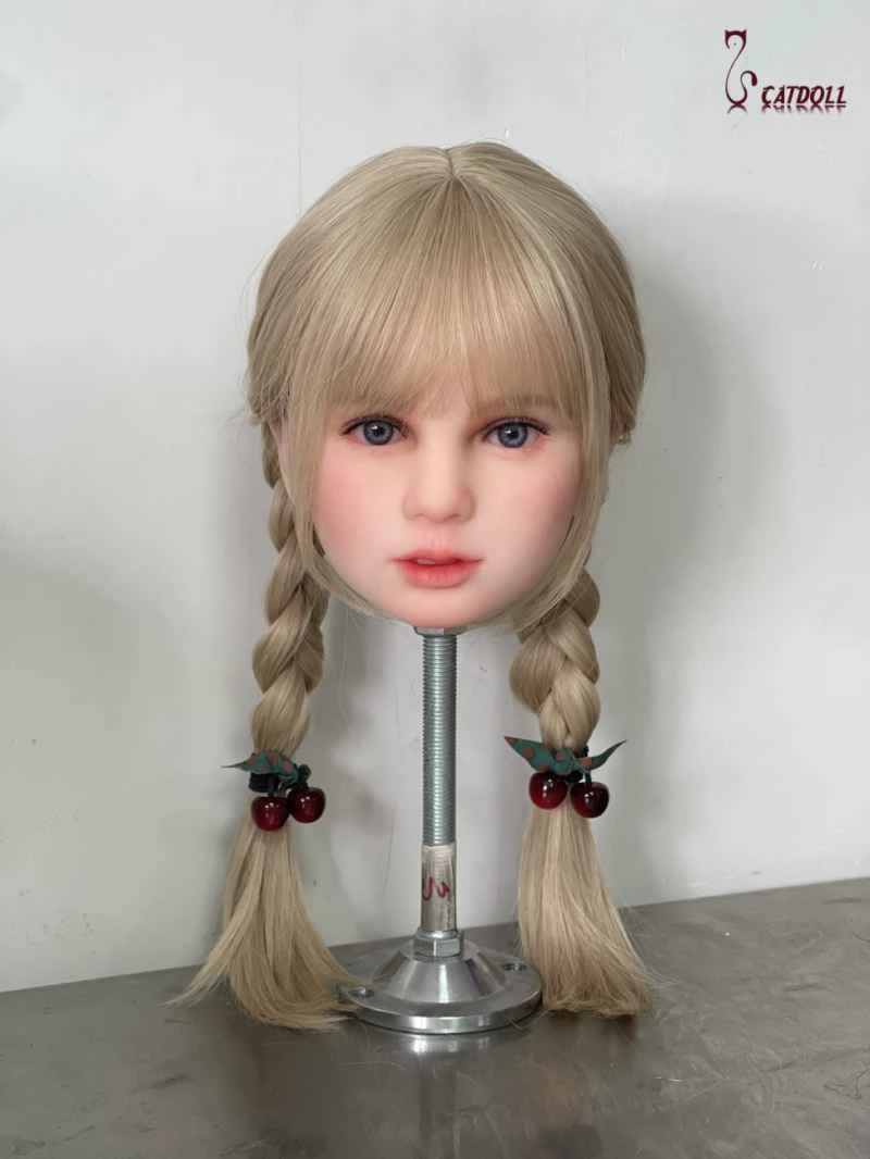
Share this

Combustion control system

2026-04-06 07:21:04 · · #1
The task of the automatic combustion control system: Designing an automatic boiler combustion control system : The purpose of the control system is to control the combustion process, ensuring that the heat provided by fuel combustion adapts to the external demand for steam load from the boiler, while guaranteeing safe and economical boiler operation. Automatic control of the boiler combustion process mainly includes three control components: 1. Controlling the fuel quantity. When the external demand for boiler steam load changes, the amount of fuel burned (the weight of fuel fed into the furnace per unit time) must be adjusted accordingly. 2. Controlling the air supply. To achieve economical combustion, the air supply must be adjusted accordingly to match the air supply (the weight of air fed into the furnace per unit time) with the fuel quantity. The economic efficiency of the combustion process can be measured by the suitability of the excess air coefficient, which is usually indirectly expressed by the oxygen content in the flue gas. Economical combustion can also be achieved by maintaining a certain ratio between the air volume and the fuel quantity. Controlling the air supply is also for safe operation; if the air volume is too low relative to the fuel quantity, it may lead to flameout. 3. Controlling the induced draft. To maintain the furnace pressure within the required range, the induced draft volume (the weight of flue gas drawn from the furnace per unit time) must be compatible with the supplied air volume. The furnace pressure also affects the safe and economical operation of the boiler. Too low a furnace pressure will cause a large amount of cold air to leak into the furnace, increasing the load on the induced draft fan and flue gas losses; excessively low furnace pressure may even cause an implosion. Conversely, when the furnace pressure is high and exceeds atmospheric pressure, flue gas will escape, affecting not only environmental hygiene but also potentially equipment and personnel safety. Accordingly, the above three controls are achieved by three sub-control systems: the fuel quantity control system, the supplied air volume control system, and the induced draft volume control system. These three control systems are closely interrelated; to control the combustion process effectively, the fuel quantity, supplied air volume, and induced draft volume must change in a coordinated manner. During normal boiler operation, the fuel quantity and total air volume must be in an appropriate proportion; the variable representing this appropriate proportion is defined as the boiler's combustion rate. Fuel Quantity Control System The task of the fuel quantity control system is to control the fuel quantity according to the combustion rate command output by the unit load coordination control system or manually given by the operator. 1. Fuel Quantity Measurement and Heat Signal In the fuel quantity control system, the fuel quantity signal, as the feedback signal for control according to the combustion rate command, should be able to reflect the actual fuel quantity change in a timely manner. Accurate and timely measurement of fuel quantity is the key issue of the fuel quantity control system. For liquid and gaseous fuels, the amount of fuel entering the furnace can be directly measured, but for solid fuels (power plant boilers mainly use coal as fuel), it is difficult to directly measure the amount of fuel entering the furnace, and indirect measurement methods are usually used. (1) Pulverizer Speed ​​For boilers using intermediate storage pulverizing systems, the pulverizer speed can be used to indirectly represent the fuel quantity. However, the feeder speed cannot reflect the influence of factors such as coal powder gravity flow. Due to the gravity flow of coal powder, the feed rate may be different at the same speed. This deviation can only be eliminated by changing the combustion rate command when it affects the main steam pressure or unit load. (2) Differential pressure between the inlet and outlet of the coal mill For boilers using a direct-fired pulverizing system, the differential pressure between the inlet and outlet of the coal mill can be used to approximate the fuel quantity. This is based on the assumption that the output of the coal mill is proportional to the square root of its inlet and outlet differential pressure. However, many factors affect the differential pressure between the inlet and outlet of the coal mill (such as coal type, primary air volume and coal mill operating conditions), and the fluctuation of this signal is also large. (3) Feeder speed For boilers using a direct-fired pulverizing system, the fuel quantity can also be calculated using the feeder speed. While requiring good adjustment of the feeder speed, the influence of coal bed density and thickness on the fuel quantity should also be considered to maintain a definite relationship between the coal feed rate and the speed. The above three methods are methods for measuring coal quantity. Sometimes, in order to maintain stable combustion in the furnace, oil is burned while coal is burned. Therefore, the measurement of total fuel quantity actually includes the measurement of fuel oil quantity and the measurement of coal quantity. (4) Heat signal Measuring the heat of combustion of fuel entering the furnace is a method of indirectly measuring the amount of fuel entering the furnace. Whether a direct-fired or intermediate-storage pulverizing system is used, the amount of fuel entering the boiler can be represented by the heat signal. Basic structure of fuel quantity (coal quantity) control system The simplest fuel quantity control system can use the combustion rate command output by the boiler controller of the load main control system or the combustion rate command manually output by the operator from the coal control station to directly control the actuator of the fuel system and change the amount of fuel entering the boiler. However, if the fuel quantity measurement signal is not introduced into the system, this scheme cannot quickly eliminate the disturbance when fuel disturbance occurs. Only when the main steam pressure or unit load changes can the fuel quantity be adjusted by changing the combustion rate command through the load main control system or by the operator to finally eliminate the disturbance. Therefore, fuel quantity control systems generally use the fuel quantity measurement signal as the feedback signal. The fuel quantity regulator controls each fuel quantity adjustment mechanism in parallel based on the combustion rate command and the fuel quantity feedback signal. The differences between different fuel quantity control systems mainly lie in the fuel quantity signal measurement method and the adjustment characteristics of the fuel quantity adjustment mechanism. The fuel quantity measurement issue has been introduced earlier. The structural scheme of the fuel quantity control system is also related to the selection of pulverizing equipment and the design of the pulverizing system. Pulverizing systems are divided into two main categories: intermediate storage type and direct-fired type. For intermediate storage type pulverizing systems, the fuel quantity can be adjusted by adjusting the speed of the pulverizer. Because of the intermediate storage, the dynamic response of fuel quantity adjustment is faster, and therefore the system structure is relatively simple. For direct-fired pulverizing systems using medium-speed mills, there is a significant delay from coal feeding into the mill to coal powder output. To improve response speed, the control system can first adjust the primary air volume according to the combustion rate command, and then adjust the feeder speed according to the ratio of primary air volume to coal feed rate, thus changing the coal feed rate. This is the combustion rate command/primary air volume/fuel quantity control scheme, as shown in Figure 11-5. The advantage of this control scheme is its fast load response speed. When the combustion rate command changes, immediately changing the primary air volume can quickly remove the coal powder stored in the mill, thereby achieving a rapid response to the load command. However, disturbances in the primary air volume, especially those caused by the mill temperature control system, will frequently affect the primary air volume, which in turn will frequently affect the fuel quantity. Furthermore, this scheme essentially combines the primary air volume control system and the fuel quantity control system into one system, making the system more complex. Another scheme is the combustion rate command/fuel quantity/primary air volume control scheme. This scheme directly controls the coal feed rate according to the coal feed command generated by the combustion rate command; the primary air volume control system controls the primary air volume according to the ratio of primary air to fuel. Simultaneously, a differential element dynamically overshoots the primary air volume, promptly blowing a portion of the pulverized coal stored in the pulverizer into the furnace. This allows for rapid adaptation to load changes when increased load is required. Conversely, during load reduction, to prevent the actual primary air volume from falling below the required primary air volume for the coal feed rate, a primary air volume command is used to limit the coal feed rate command, thus preventing coal blockage due to insufficient primary air. (Edited by: He Shiping)
Read next

CATDOLL 126CM Sasha

Height: 126cm Weight: 23kg Shoulder Width: 32cm Bust/Waist/Hip: 61/58/66cm Oral Depth: 3-5cm Vaginal Depth: 3-15cm Anal...

Articles 2026-02-22