Read next
The hazards of vacuum circuit breaker closing bounce and countermeasures
Abstract: The "General Technical Conditions for 35kV Indoor High-Voltage Vacuum Circuit Breakers" (ZBK97004-89...
Articles
2026-02-22

CATDOLL Oksana 109CM TPE (Soft Silicone Head)
Articles
2026-02-22
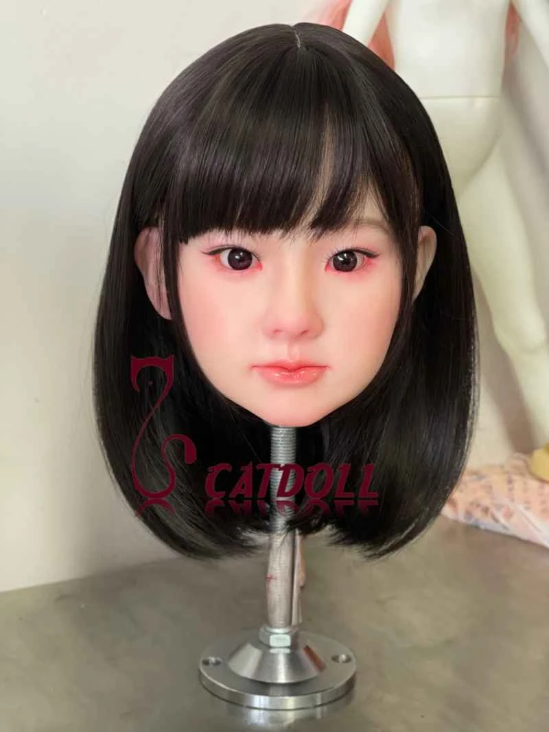
CATDOLL Miho Soft Silicone Head
Articles
2026-02-22

CATDOLL 102CM Li Anime Doll
Articles
2026-02-22