Share this

Design based on Atmega128 embedded controller

2026-04-06 06:00:21 · · #1
Abstract: An embedded controller based on Atmega128 microcontroller is designed. The analog input channel uses the on-chip A/D converter of Atmega128, the output uses AD421 D/A converter, and the digital I/O channel is configured with high-speed precoupled devices. The OSTaskStklnit() function and related files are modified using the lccavr compiler to define data types and achieve MicroC/OS-II porting. Keywords : Atmega128; embedded controller; CANBus; Micro C/OS-II Design of Embedded Controller Based on Atmega 128 YU Gui-jun, XI Chong-hua (College of Information & Control Engineering, Southwest University of Science & Technology, Mianyang 621 002, China) An A/D converter in Atmega 128 is adopted in the analog input channel, and an AD421 D/A converter is used in the output channel. A high-speed photocoupler is used in the digital input and output channels. The OSTaskStklnit() function and correlative files are modified with the Iccavr compiler. Data type is defined to realize the transplant of Micro C/OS-II. Key words: Atmega 128; Embedded controller; CANbus; Micro C/OS-II 1 Introduction Embedded controllers are the core components for the automation of electromechanical equipment. Therefore, taking large electromechanical equipment as the control object, a multifunctional embedded intelligent controller with fieldbus (CANBUS) network communication and certain versatility is designed using the high-performance Atmega 128 microprocessor. 2 Hardware Design The hardware structure of the system is shown in Figure 1. The core of this controller uses the Atmega128 chip in a 64-pin TQFP package, which has 53 programmable I/O pins and integrates 128KB flash memory, 4KB EEPROM and 4KBSRAM, suitable for the needs of I/O channels and storage space. (1) Analog Input Channel The analog input channel uses the 8-channel 10-bit A/D converter on the Atmega128 chip. Its signal input section can select the multi-function input signal conditioning circuit shown in Figure 2 according to the specific signal conditions. When the voltage signal is input, R1 and C can form a low-pass filter (R2 open); R1 and R2 can form an input signal voltage divider circuit (capacitor C open); for a 4-20mA current input signal, R2 can be converted into a 1-5V signal by using a 250Ω precision resistor (R1 short, C open). The circuit board is designed with the corresponding multi-function signal conditioning circuit soldering positions, which can be selected and used as needed. The 8-channel analog input section occupies PF0 to PF7 of the ATMEGA128. (2) Analog Output Channel The circuit design scheme of the analog output channel unit is shown in Figure 3. The D/A converter uses AD421 from AD company, which is a single-chip low-power, high-precision current output DAC chip. The 4-20mA output can drive standard actuators. The digital interface of this chip is standard HART (three-wire) or other FSK protocol. The DAC has a 16-bit resolution and monotonic output. The loop power supply method is adopted, and the power regulator is included to power itself and peripheral devices. In industrial control, the input quantity is usually more than the output quantity, so only PAO to PA7 of Atmega128 are designed. The PE2, PE3, PE6 and PG4 pins are connected to 4 AD421 through 4 opto-isolators (6N137) to form 4 analog outputs. (3) Digital Input/Output Channel Each digital I/O channel is configured with 8 high-speed optocoupler isolation channels. The optocoupler device is 6N137, whose switching delay tpd is only 75ns, while the switching delay of ordinary optocoupler devices is 3-6μs. The I/O channel interfaces are arranged on PB0~PB7 and PD0~PD7 of Atmega128. (4) CAN bus interface An independent CAN communication controller SJA1000, CAN bus driver 82C250 and high-speed optocoupler 6N137 are selected and designed with microcontroller Atmega128. The microprocessor Atmega128 is responsible for the initialization of SJA1000 and realizes communication tasks such as data reception and transmission by controlling SJA1000. The CAN bus interface is shown in Figure 4. AD0~AD7 of SJA1000 are connected to the PC port of Atmega128, and CS is connected to PG3 of Atmega128. When PG3 is 0, the CPU selects SJA1000 for external memory address, and the CPU can perform read/write operations on SJA1000 through the address. The RD, WE, and ALE pins of SJA1000 are connected to the pins of Atmega128, and INT is connected to PE7 of Atmega128. Atmega128 can access SJA1000 through interrupt. (5) Serial communication with PC Considering that the intelligent control node needs to receive data from the RS232 serial port, the serial port of Atmega128 is used for interrupt reception, and the pins used are PE0 and PE1. Data transmission is performed through MAX232. (6) Pulse input and pulse output Due to the diversity of input signals, the PI/PO part is added. 3 Porting of Micro C/OS-II To port Micro C/OS-II to Atmega128, it is necessary to modify three related files: OS_CPU.H, OS_CPU_A.S, and OS_CPU_C.C. Among them, OS_CPU.H mainly completes the definition of data type, stack unit, and stack growth direction. Related data type definitions: `typedef unsigned char BOOLEAN;` `typedef unsigned char INT8U;` // Unsigned 8-bit `typedef signed char INT8S;` // Signed 8-bit `typedef unsigned int INT16U;` // Unsigned 16-bit `typedef signed int INT16S;` // Signed 16-bit `typedef unsigned long INT32U;` // Unsigned 32-bit `typedef signed long INT32S;` // Signed 32-bit `typedef float FP32;` // Definition of single-precision floating-point stack unit: `typedef unsigned char OS_STK;` // Definition of 8-bit status register: `typedef unsigned char OS_CPU_SR;` // Definition of 8-bit status register and stack growth direction: `#define OS_STK_GROW TH 1;` // AVR stack grows from high address to low address. The C file mainly includes task stack initialization and implementation of several hook functions specified by the operating system. The hook functions required for porting are as follows: OSTaskCreateHook(); OSTaskDelHook(); OSTaskldleHook(); OSTaskStateHook(); OSTaskSwHook(); OSTCBInitHook(); OSTimeTickHook(). The functions from OS-CPU-A.s required for porting are: OS_CPU_SR_SAVE(); OS_CPU_SR_RESTORE(); OSStartHightRdy(); OSCtxSw0; OSIntCtxSw(); OSicklSR0. The controller is verified using the ported embedded operating system, selecting PB0~PB7 as inputs and PD0~PD7 as outputs, to demonstrate diode illumination. Partial source code is as follows: static void LED_Toggle(INT8U led) { #if OS_CRITICAL_M ETHOD = = 3 //Allocate storage for CPU status register OS_CPU_SR cpu_sr; #endif OS_ENTER_CRITICAL(): switch(1ed) {casc 1: PORTD⌒=0x01; break; case 2: PORTD⌒= 0x02; break; case 3: PORTD⌒= 0x04; break; case 4: PORTD⌒= 0x08; break; } OS_EXIT_CRITICAL(); } 4 Conclusion The embedded controller designed using Atmega128 can complete multi-functional data acquisition and control, CAN bus and RS232 communication, and the ported embedded real-time operating system can enhance the real-time multi-task information processing capability. The design was verified through experiments. References: [1] Geng Degen, Song Jianguo, Ma Hu, et al. Principles and Applications of AVR High-Speed ​​Embedded Microcontrollers (Revised Edition) IM1. Beijing: Beijing University of Aeronautics and Astronautics Press, 2002. [2] Shao Beibei, et al. Real-time Embedded Operating System with Open Source Code of uC/OS-II [M]. Beijing: China Electric Power Press, 2001. [3] Rao Yuntao, Zou Jijun, Zheng Yongyun. Principles and Applications of Fieldbus CAN [M]. Beijing: Beijing University of Aeronautics and Astronautics Press, 2003.
Read next

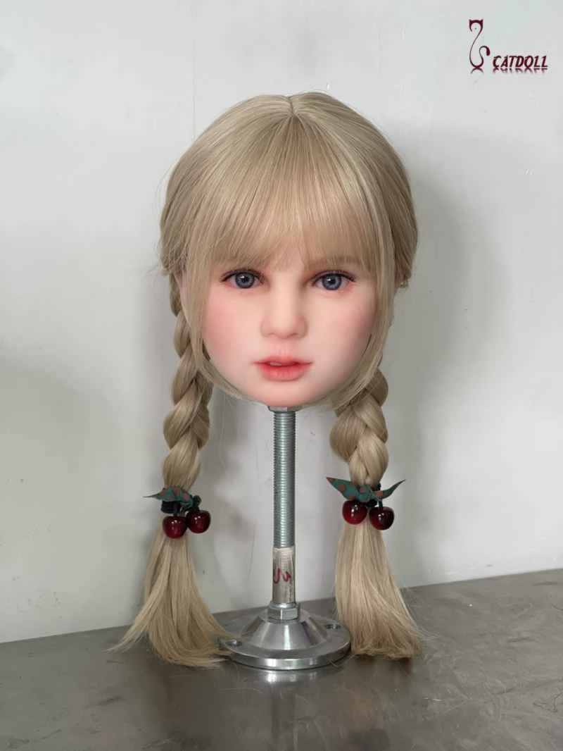
CATDOLL Luisa Hard Silicone Head

The head made from hard silicone does not have a usable oral cavity. You can choose the skin tone, eye color, and wig, ...

Articles 2026-02-22