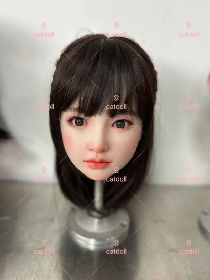
Implementation of communication and real-time control between host computer and PLC
2026-04-06 04:29:30··#1
1. Introduction In industrial control, programmable logic controllers (PLCs) are widely used due to their advantages such as strong control capabilities, small size, strong anti-interference ability, high reliability, and ease of use, and have become one of the main technology platforms for modern industrial control. In practical applications, it is often necessary to use a PC to set or modify a small number of parameters in the PLC control program, which necessitates solving the communication problem between the PC and the PLC. This paper discusses the communication problem between the PLC and the PC based on the practical application of communication between the PLC and the host PC in the control system of a steaming machine. The system block diagram is shown in Figure 1. 2. Scheme Overview The steaming machine is a widely used piece of equipment in the textile industry. Its workflow is as follows: opening the door of the autoclave; the trolley exits from the autoclave; the beam (shaft) is mounted on the star-shaped component; the star-shaped component rotates; the beam is mounted on the trolley; the trolley enters the autoclave; the autoclave door closes; and the system circulates within the autoclave. In the control of the steaming machine, the Siemens S7-200 series PLC can meet the requirements, and the system cost should be kept as low as possible. On the host computer side: Since the amount of data to be controlled is not large, using dedicated configuration software would be too costly. Based on this approach, we used VC++ to develop a serial communication program on the host computer for data transmission and control. Generally, the S7-200 series communication ports have four operating modes: PPI, MPI, PROFIBUS, and freeport communication. PPI mode can only communicate in PLC stop mode (STOP), while freeport mode can only communicate in PLC run mode (RUN). The CPU's serial communication port can be controlled by the user program; this operating mode is called freeport mode. When freeport mode is selected, the user program can control the operation of the serial communication port through transmit interrupts, receive interrupts, transmit commands (XMT), and receive commands (RCV). In freeport mode, the communication protocol is entirely controlled by the user program. Because the communication protocol can be completely controlled by the ladder diagram program in freeport mode, and receive interrupts, transmit interrupts, transmit commands, and receive commands can be used to control communication operations, freeport communication mode is chosen. 3. Host Computer (PC) Control Program Programming 3.1 Initialization The host computer control program is written according to the following steps: (1) Create an MFC application based on a dialog box; (2) Insert the MSComm control into the dialog box; (3) Define the CMSComm class control object using ClassWizard; (4) Add the MSComm control to the dialog box and assign variables; (5) Open the serial port and set parameters: The task to be completed is to select and open the serial port, specify the baud rate, parity type, data bits, stop bits and other control information; if (m_ctrlComm.GetPortOpen()) m_ctrlComm.SetPortOpen(FALSE); m_ctrlComm.SetCommPort(1); // Select com1 if (!m_ctrlComm.GetPortOpen()) m_ctrlComm.SetPortOpen(TRUE); // Open the serial port else AfxMessageBox("cannot open serial port"); m_ctrlComm.SetSettings("9600,n,8,1"); // Baud rate 9600, no parity, 8 data bits, 1 stop bit // The settings here should match the communication parameters of the lower-level machine. Generally, they are set according to the specific situation of the lower-level machine. m_ctrlComm.SetInputMode(1); // 1: indicates that data is retrieved in binary mode. m_ctrlComm.SetRThreshold(1); // SetRThreshold(1); // Parameter 1 indicates that the OnComm event for receiving data will be triggered when there are more than or equal to 1 character in the serial port receive buffer. m_ctrlComm.SetInputLen(0); // Set the current receive area data length to 0. m_ctrlComm.GetInput(); // Read the buffer first to clear residual data. (6) Add the serial port event message handling function OnComm. This function handles serial port message events. Whenever data is received from the serial port, a message event indicating that a character exists in the serial port receive data buffer is generated, which executes the function we just added. Adding the corresponding processing code to the OnComm() function will achieve the desired functionality. 3.2 Control Data Processing: Control data is stored. During programming, initial values (default values) are assigned to the control variables. Each time the host computer control program runs, the control data is read and sent to the corresponding control unit. Even if it's the first time the program is run, clicking "Run" will retrieve the control data from the file and synchronously send it to the lower-level machine. Each time the control data is changed, it is saved as the new default control data for use when starting the device later. Here, we want to implement the function of controlling the start and stop of the lower-level machine, as well as setting the timing length of three timers. The sent data includes the start/stop flag of the lower-level machine, the timing length of the three timers, and the control information end flag. It is important to note that an end flag must be added at the end of the control information. This end flag is specified on the PLC and requires the cooperation of the host computer. Its function is to generate a reception completion interrupt upon receiving the flag, thereby responding to the control from the host computer. The specific operation is as follows: Sending data: A click message is triggered by the send button to read the contents of the edit box, save the read data to a file, and send the data to the serial port. UpdateData(TRUE); // Read the content of the edit box CFile OutFile; OutFile.Open(pFileName, CFile::modeCreate| CFile::modeWrite); OutFile.SeekToEnd(); CArchive ar(&OutFile, CArchive::store); UpdateData(true); ar << m_strTXData << ar.Close(); OutFile.Close(); // Close the file CtrlData = MachineState + m_strTXData + m_strTXData2 + m_strTXData3 + EndFlag; // Control data MessageBox("Send given data?", "Send prompt!", 0 + 48 + 512); // Add a message prompt box m_ctrlComm.SetOutput(COleVariant(CtrlData)); // Send data CtrlData = ""; Additionally, the start and stop buttons will also trigger click messages. The processing method is similar to the data sending process described above, except that MachineState must be set first: set to 1 for start and 0 for stop, to start or stop the device; and no further operations are performed on the file storing control data. 4. Lower-level computer (PLC) control program programming 4.1 Initialization and setting of serial port communication parameters. Interrupts must be generated upon completion of receiving and sending, with interrupt numbers 9 and 23 respectively. main: NETWORK 1 LD SM0.1 MOVB 16#09, SMB30 // Free port parameters: no parity, 8 data bits, baud rate 9600, free port communication; MOVB 16#B0, SMB87 // Receive information control, start receiving function, detect information end flag; MOVB 16#2A, SMB89 // Define information end flag, cooperate with host computer; MOVW +5, SMW90 // Idle line time limit, unit microseconds; MOVB 100, SMB94 // Maximum number of characters received ENI // Enable interrupt ATCH INT_0, 23 // Receive interrupt connection ATCH INT_2, 9 // Transmit interrupt connection RCV VB100, 0 4.2 Control main program NETWORK 1 LDB= VB101, 16#31 // Detect control information requiring machine start, transfer to start operation LPS S V10.0,1 // Set start flag bit A V10.0 // Check start flag A I0.1 // Check if input is 1 TON T51, VW600 // If all conditions are met, start the timer, whose timing parameters are given by the host computer A T51 A V10.0 // If the timer expires and the slave device is in the start state, set the output Q0.4 = Q0.4 NETWORK 2 LDB= VB101, 16#30 A V10.0 S V10.0, 1 This program judges the start and stop control bits of the received control data, and decides whether to start or stop the device based on the judgment result; this program also sends the time data sent by the host computer to the timer; in this way, the host computer can control the start and stop of the slave device in real time, and can modify the timing length of the timer in real time to realize remote control. 4.3 Interrupt Handling INT_0: // Receive completion interrupt If the receive status shows that the end character has been received, connect a 10ms timer. // Send, and simultaneously convert the control data part of the received control information for subsequent program applications. LDB = SMB86,16#20 MOVB 10,SMB34 BTI VB102, VW600 // Data conversion, from ASCII to integer data -I 16#0030, VW60 0 // Perform calculations on the integer data to obtain the data seen by the operator *I +10, VW600 ATCH 1,10 CRETI NOT RCV VB100,0 // If the receive is complete, then start a new receive. In this program, the received data information part is converted and calculated. Because the default data received and sent by the lower-level machine is text information in ASCII code value format, if you want to get the value given by the user on the upper-level machine, convert it into an integer and then use this data for control. 4.4 Precautions One point to note during programming is the switching time between the receive and send modes. When communicating via the 485 communication port, the system cannot immediately switch to receive mode after sending; there is a reaction time. Therefore, if you need to send data after receiving, you need to set a timer to delay the sending operation for a certain period, and vice versa. The flowchart of the main program and each interrupt service routine is shown in Figure 2. 5 Conclusion The host computer's operating interface is shown in Figure 3. This interface allows for the start and stop control of the lower-level machine, as well as the modification of control parameters, and online parameter modification. In this project, the number of control points of the controlled object is not large, and the human-machine interaction is not extensive. The functions are relatively independent, forming a small system. In this case, this solution effectively saves investment, simplifies control, facilitates maintenance, is easy to operate, and ensures the real-time performance of the control system. Its advantages are particularly evident in small control systems, especially when the amount of data interaction is limited.