Share this

Analysis of Design Methods for Eliminating Interference and Noise in RS-232 Serial Communication

2026-04-06 05:17:04 · · #1
1. Insulation Design Methods for Communication Lines The high noise (interference) tolerance of RS-232 ensures reliable interface operation and avoids data errors caused by external noise applied to the wires. In a connection environment filled with electronic noise, insulation prevents noise coupling between connected circuits. Insulation works by dividing a circuit into independent blocks. These blocks use optical and magnetic coupling to transmit energy and data, filtering out most of the noise. Insulation can separate ground wires, data connections, or both. Ground wire insulation makes a circuit immune to power supply oscillations and noise in a ground wire shared by nearby circuits. In long connections, ground wire insulation also makes the connection immune to ground potential differences from one end to the other. Insulated data connections prevent noise coupling between the connection and the circuits it is connected to. Most circuit connections use direct methods, such as solder joints or mechanical connections such as nut terminals or crimps. Using plated insulation, the ground and signal lines of a circuit have no resistive path or direct contact with other circuits. Instead, the circuit can use optical or magnetic coupling to transmit energy and signals. Insulation also makes each circuit immune to noise from another circuit. Common methods for achieving electroplated insulation include using transformers to insulate the power supply and using optical isolators to isolate data. In a transformer, magnetic coupling between coil windings causes current in the primary coil to flow into current in the secondary coil. Optical isolators transmit energy via photoresistors and photodiodes that release and detect energy in the visible or infrared bands. Similarly, an optical fiber-optic interface converts two electrical signals into optical signals that are transmitted through the fiber, and the receiver converts the optical signals back into electrical signals. For complete insulation, each end of an RS-232 connection requires an isolated power supply for the RS-232 interface and an isolated interface to transmit the signal through the insulating barrier. In an RS-232 connection, SG is signal ground. Because the RS-232 receiver reads the voltage between the signal line and SG, a noise pulse on SG can cause the receiver to misread a logic level. In digital logic, +5V is a simplified way of saying a voltage 5V above signal ground. When a circuit uses more than one power source, even if the power source grounding wires are not mutually insulated, keeping the grounding paths independent reduces noise coupling from one path to another. Each power source's grounding wire can use a separate wire and circuit board, as long as they are connected together at the power source. Circuits containing analog and digital circuits can provide separate grounding wires for each type of circuit, connecting both paths at a single point near a power source. Digital grounding wires are often noisy because digital outputs generate large currents when switching, so it's reasonable to separate them from analog circuits, which may be sensitive to small voltage changes. 1.1 Safety Ground The safety ground, or protective ground, is a single earth connection, typically a large-diameter copper conductor or copper-plated conduit buried underground. One of the three wires on a power outlet is connected to the safety ground. The other two wires are a live wire carrying 220V AC voltage and a neutral wire carrying a 220V AC return current; the neutral wire is connected to the safety ground. This means that the neutral wire of all building circuits typically has a connection to the building at the entrance. The safety ground wire provides a low-impedance path to ground in the event of a fault. For example, in many power supplies, there is a terminal connecting the safety ground wire to the power supply chassis. If the chassis is not grounded and a loose wire or component failure causes a voltage source to come into contact with the chassis, the chassis may carry a high voltage. If the chassis is grounded, current will flow along this low-impedance path to the ground until the fuse blows and the circuit breaks. In the TIA/EIA-232 standard, a DCE can have a movable jumper to connect the SG and the safety ground wire. In practice, the SG wire on both the DCE and DTE is often connected to a safety ground wire. 1.2 Earth Ground Wire A safety ground wire is an earth ground wire. Because any electrical circuit can be connected to the earth ground wire, it is often not a quiet, stable reference; instead, it can carry a significant amount of various types of noise. Factors that can generate grounding noise include equipment switching, power system fluctuations, circuit faults, lightning strikes, or any event that causes current fluctuations. Noise can manifest as tilt angles, spikes, 60 Hz vibrations, or any form of magnetic or electric field variation. Earth ground wires at different locations may or may not be electrically connected. Whether they are connected, and how much the grounding voltage varies, depends in part on the conductivity of the medium between the ground wire connections. 1.3 Effects of a Shared Ground Wire If both ends of an RS-232 connection share a common earth ground wire, and the SG line is also connected to the safety ground wire, grounding currents from all sources will seek the path of lowest impedance: the earth ground wire or the SG line. In this case, there are multiple return paths, called a ground loop, which is obviously undesirable. If the two devices are located in different buildings and use different power systems, the SG line may have a lower impedance than other paths, and grounding currents from other sources may find their path on the connected ground wire, resulting in a noisy ground wire in the connection. A connection with an insulated ground wire avoids this problem. 2. Design and Application of Power Ground Wires An insulated interface requires a power supply at each end of this insulating barrier. Figure 2 shows two insulated RS-232 interfaces. Each interface uses a dual power supply, as shown in Figure 1. In this power supply, a transformer converts 220 V AC to a lower voltage in two secondary coils. One coil provides voltage to the circuitry at the end of the computer or other device connected to the opto-isolator. The other coil provides voltage to the RS-232 interface. Each power supply has its own ground wire, and these ground wires must not share a common connection with a main ground, chassis, or signal ground. This interface can use two completely separate power supplies or batteries whose outputs do not share a common ground, instead of a single power supply with two coils. How do you determine if a DC power supply is insulated from the main ground wire? In most DC power supplies powered by line voltage, a transformer steps the line voltage down to a lower value, and other components rectify, filter, and regulate this voltage output to a stable DC voltage value. The only connection required between the primary and secondary coils of the transformer is the magnetic coupling generated when current flows in the primary coil. In this way, the transformer can insulate the power output from the line voltage conductor and the safety ground. In reality, some digital circuit power supplies do not have their outputs connected to the safety ground. At the output, because the voltage is very low, the regulator limits the current, and if the circuit attempts to generate a large current, a fuse will trip the circuit. In other power supplies, the output grounding terminal is connected to a safety ground, breaking this insulation. The result is a shared ground with other circuits that are still connected to safety ground or earth ground. Even if these circuits are in different buildings or thousands of feet apart, there may be a connection between them. A power supply with a two-prong outlet may appear to have no safety ground connection, but the neutral wire is connected to the safety ground when an external circuit is plugged into the power supply. The output of this power supply is only insulated when its ground wire is not connected to the neutral wire. For power supplies containing transformers, an ohmmeter can be used to check if the output is insulated from the safety ground. Using the power supply, measure the impedance between the power supply's safety ground and the grounding terminal of the DC output. If the ohmmeter shows a connection, it means there is no insulation. Internally, the neutral and safety ground wires should not be connected. This can be verified with an ohmmeter. Some power supplies do not use transformers; they simply rectify directly, reducing and filtering line voltage. In this case, the output is not insulated from the earth ground. Even if the power socket does not have a safety ground pin, the neutral wire is connected to the safety ground when an external circuit is plugged into the power supply. 3. Using Opto-Isolators Opto-isolators transmit signals through an isolation barrier. An opto-isolator consists of a light-emitting diode (LED) coupled to a photoresistor. The current flowing through the LED causes it to release energy in the form of visible or infrared light. This energy turns on the photoresistor, resulting in a low impedance between the emitter and collector of the resistor. The base of the LED can be left unconnected. Adding a resistor from the base to the emitter results in faster switching speeds but lower output current. The interface in Figure 2 uses a 6N1398 opto-isolator, designed for direct connection to LSTTL logic. They have gains up to 400%, but the current drawn by an LED is only 0.5 mA. In a TTL to RS-232 circuit, a logic low on pin 3 of the 74LS14 converter causes current to flow through the LED, which in turn turns on the corresponding photoresistor, causing its collector to go low. The MAX233 inverts this signal and then sends a positive RS-232 voltage. A logic high on pin 3 of the 74LS14 turns off the LED and photoresistor. The internal pull-up resistor on pin 2 of the MAX233 generates a negative RS-232 voltage. The opto-isolator operates similarly in the other direction. A negative RS-232 input causes the MAX233 to output a logic high. This logic high turns on the LED and photoresistor, resulting in a logic low on pin 1 and a logic high on pin 2 of the 74LS14. A positive RS-232 input causes the MAX233 to output a logic low. This logic low turns off the LED and photoresistor. A pull-up resistor pulls pin 1 of the 74LS14 high, resulting in a logic low at pin 2. The RS-232 to RS-232 circuit demonstrates how to isolate an existing, unisolated RS-232 interface by directly driving an LED using an RS-232 output. When the RS-232 voltage is positive, the LED is on, and the isolated RS-232 output is also positive. When the unisolated output is negative, the LED is off, and a diode limits the voltage to approximately -0.7 V. In the other direction, the circuit is similar to the one above, except that because the unisolated RS-232 has already inverted the signal, an LS74 series inverter is not required. For VCC1 in the bottom circuit, a positive output can be used in the DTR or RTS if there is no other purpose. The cable on the VCC1 side of this circuit should be shorter. The switching time of a photoresistor is a few microseconds, a duration that will not cause any problems at data transmission speeds of 20 kb/s or lower. For faster baud rates, an LED with a switching time of 1/10th of the bit width or less should be sought. Another method to achieve an isolated interface is to use a separate, isolated +12 V power supply for the RS-232 end of the interface. This also allows the use of cheaper 1488/9 drivers and receivers. Alternatively, the Max252 interface can be used; the Max252 is a complete, isolated RS-232 interface in a single package. This chip includes a quartz resonator and a miniature transformer that generates an isolated power supply from the chip's 5 V power supply. It also has two optically isolated driver/receiver pairs. Another way to achieve an isolated connection is to use fiber optic cables instead of copper wires. Fiber optics have many advantages; they are resistant to ground noise and electromagnetic interference and do not generate electromagnetic interference themselves. Fiber optic cables often do not require repeaters after 1–2.5 mils. 4. Surge Protection Design Surge protection is an effective way to protect circuits from noise or destructive voltage and current attacks. Ideally, surge protection should absorb all voltages and currents outside the operating range of the connection without limiting the transmission of the connection in any way. In practical engineering applications, capacitors can be added to the connection to avoid adverse effects due to voltage fluctuations, thus limiting the maximum baud rate. During normal operation, this protection device exhibits a very high resistance, so it is practically invisible to the transmission circuit. When a high voltage inrush current occurs on the line, the protection device opens, providing a resistive path to ground. Two useful inrush current suppression devices are TVS diodes and gas-cooled tubes. TVS (Transient Voltage Suppressor) diodes have a very small capacitance when off and react quickly (10-12 seconds) and can be used over a wide breakdown voltage range. Gas-cooled tubes are slower but can provide protection at higher voltages. Some connections use both. Each device should be connected through a grounding jumper or other low-impedance connection directly to the earth ground wire. References : 1. Mark Nelson (USA). Serial Communication Development Guide. Beijing: China Water Resources Press, 2000, 9. 2. Jan Axelson (USA). Serial Port Guide. Beijing: China Electric Power Press, 2001, 5. 3. Fan Yizhi. Visual Basic and RS-232 Serial Communication Control. Beijing: China Youth Press, 2000, 8.
Read next

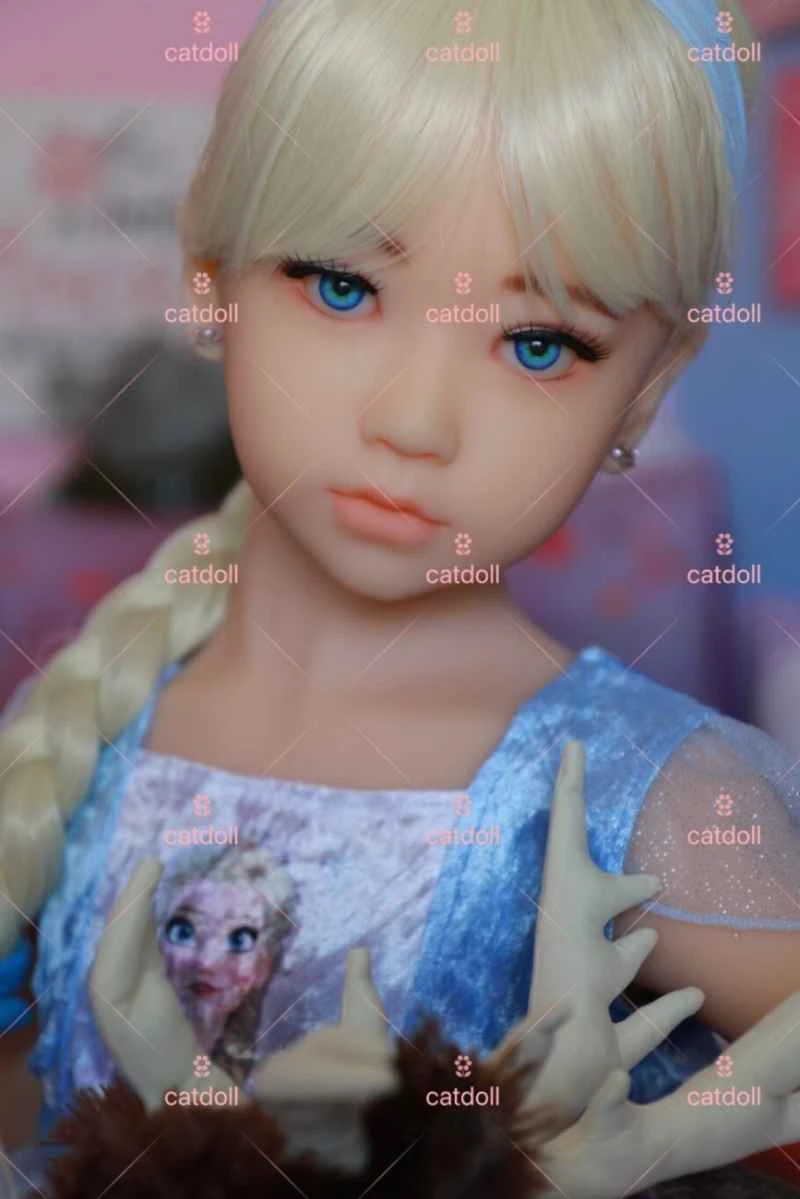
CATDOLL 131CM Kelsie (TPE Body with Hybrid Silicone Head)

Height: 131cm Weight: 25.5kg Shoulder Width: 32cm Bust/Waist/Hip: 67/56/72cm Oral Depth: 3-5cm Vaginal Depth: 3-15cm An...

Articles 2026-02-22