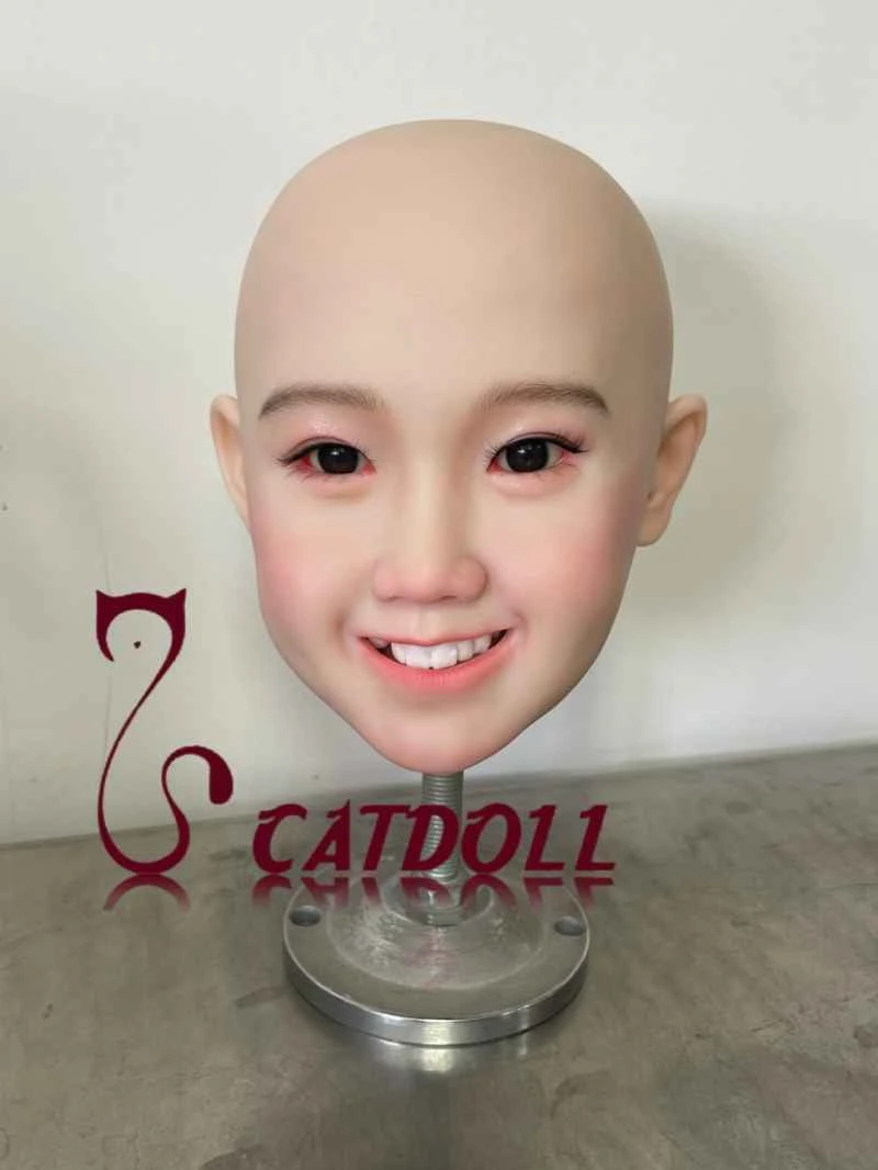
Design and Implementation of Orchard Meteorological Monitoring Network Node Based on CAN Bus Technology
2026-04-06 06:21:31··#1
Abstract: This paper introduces a distributed orchard meteorological monitoring system based on CAN bus, focusing on the characteristics of the P87C591 microcontroller and the implementation of monitoring network nodes using it as the control core. Keywords: CAN bus, meteorological monitoring, P87C591, I2C bus. The growth of fruit trees is affected by both natural environment and human factors, among which meteorological conditions in orchards have a significant impact on the growth, fruiting, and lifespan of fruit trees. Orchard meteorological conditions include temperature, soil moisture, sunlight, and wind strength. Therefore, monitoring orchard meteorological conditions and promptly improving fruit tree growth conditions based on human factors has become a key issue affecting fruit farmers' income. CAN bus is a serial data communication protocol developed by Bosch in Germany in the early 1980s to solve the data exchange between numerous control and testing instruments in modern automobiles. The CAN bus communication interface integrates the physical layer and data link layer functions of the CAN protocol, and can complete the framing processing of communication data, including bit stuffing, data block encoding, cyclic redundancy check, priority determination, etc., with a communication rate of up to 1 Mbps. As a distributed, digital, bidirectional, multi-point communication system with high speed and high reliability, the CAN bus can build a flexible multi-master communication mechanism and also establish a master-slave structure, and the physical hardware connections are completely identical in both methods. 1 System Overall Scheme Design and Working Principle A distributed orchard meteorological monitoring network system is constructed using the CAN bus, adopting a master-slave structure. The system structure is shown in Figure 1. This system consists of three parts: a host monitoring PC, a CAN bus adapter, and field monitoring nodes. The number of nodes can be increased or decreased according to the scale of the orchard. Figure 1 System Structure Principle Block Diagram The host monitoring PC is mainly responsible for receiving and managing meteorological data from the monitoring system, sending control commands, and displaying the real-time working status of each monitoring node; the CAN bus adapter allows the PC to be easily connected to the CAN bus; this system uses a USB-CAN bus adapter; the monitoring nodes are based on the P87C591 microcontroller, mainly responsible for collecting on-site meteorological data, performing digital filtering and averaging on the collected data, and sending the processed digital signal to the CAN bus. Simultaneously, the monitoring nodes also receive control command parameters from the host computer. This system offers reliable and fast communication, with simple hardware circuit design and software programming, effectively meeting the requirements for long-term and accurate monitoring of orchard meteorological conditions. 2. Design of the Meteorological Monitoring Node 2.1 Features of the P87C591 The node hardware circuit is based on the PHILIPS 8-bit microcontroller P87C591. The P87C591 is derived from the 80C51 microcontroller family, featuring a hardware I2C bus interface and a CAN bus interface, a 10-bit ADC with 6 analog inputs, and a selectable fast 8-bit ADC. The P87C591 incorporates the powerful PeliCAN functionality of the PHILIPS Semiconductor SJA1000 CAN controller, and extends it with the following features: ① Enhanced CAN receive interrupt, with receive buffer-level receive interrupt; a high-priority acceptance filter for receive interrupts. ② Extended acceptance filters: 8 filters for the standard frame format and 4 filters for the extended frame format; the "changeable during operation" characteristic of the acceptance filters. Figure 2 shows the block diagram of the 80C51 core and PeliCAN interface. The 80C51 CPU interface connects PeliCAN to the internal bus of the P87C591 microcontroller, as shown in Figure 2. The 80C51 core accesses PeliCAN through five special function registers: CAANADR (address register), CANDAT (data register), CANMOD (mode register), CANSTA (status register), and CANCON (command register). CANMOD allows direct read/write access to the PeliCAN mode register; writing to CANCON accesses the command register; reading from CANCON accesses the interrupt register; the CANSTA register allows write operations to the interrupt enable register; accessing CANSTA allows bit addressing and direct addressing of individual status bits, which is useful for polling. All other CAN registers require indirect addressing. The CANADR register points to the address of the PeliCAN register. During a write operation, data to be sent to the addressed register is written to CANDAT; during a read operation, data in the addressed register can be read from CANDAT. 2.2 Node Hardware Circuit Design The site requires the collection of four different meteorological information channels. Therefore, the four acquisition channels are connected to pins P1.2, P1.3, P1.4, and P1.5 of the P87C591, respectively. These four pins serve as general I/O ports and also as ADC input channels. Since the circuit uses a method of multiple acquisitions and averaging the data, a 6264 memory is used as a temporary storage area during the data acquisition process. The PCF8563 is a low-power CMOS real-time clock/calendar chip used to provide the circuit with timing interrupt signals and precise time information for data acquisition, including year, month, day, hour, minute, and second. The PCF8562 is a single-chip LCD controller/driver. Both have I2C bus interfaces and are connected to the I2C bus interface of the P87C591 in the node circuit, forming a serial transmission structure, which greatly simplifies the circuit design. After the monitoring node collects moisture, temperature, light, and wind data on-site, it will transmit the data to the host monitoring PC via the CAN bus. The P1.0 and P1.1 ports of the P87C591 are multiplexed as the input pins of the CAN receiver and the output pins of the transmitter. These two pins are connected to the CAN bus cable via the PCA82C250 transceiver. The PCA82C250 transceiver is the interface between the CAN protocol controller and the physical transmission line. The node hardware circuit is shown in Figure 3. 3. Monitoring Node Software Design In addition to initializing the P87C591 and its peripheral devices, the monitoring node software has two other tasks to complete: first, to generate timed interrupts to sample and process data from each sensor and upload the data to the host computer; second, to receive control parameter commands from the host computer via interrupts. In the timed acquisition interrupt task, the required data is sampled multiple times and averaged, while the start and end times of the acquisition are read from the clock chip, and finally sent to the LCD for display and uploaded to the host computer. Figure 3: Block diagram of the monitoring node hardware circuit. Figure 4: CAN controller initialization flowchart. The CAN controller inside the P87C591 must undergo corresponding initialization processing after power-on or hardware reset. Initialization mainly includes setting the operating mode, receiving and filtering mode, receiving mask register and receiving code register, baud rate parameter setting, and interrupt enable register setting. After completing the initialization settings, it can return to the working state to perform normal communication tasks. Figure 4 is the CAN controller initialization flowchart. Figure 5 is the node program flowchart. When there is no data acquisition task or a requirement to receive control parameters, the P87C591 enters idle mode. When a timed acquisition interrupt or a control parameter reception interrupt occurs, the P87C591 exits idle mode and enters the corresponding interrupt service routine. 4 Conclusion The author's innovation lies in proposing a good design scheme for simplifying the circuit design of data acquisition and monitoring nodes in a distributed measurement and control system node based on the CAN bus, utilizing the rich on-chip integrated resources of the P87C591. This provides a good reference for the design of similar distributed monitoring system nodes. References [1] P8xC591_useIN_CAN. www.zlgmcu.com [2] Rao Yuntao, Zou Jijun, Zheng Yongyun, eds. Fieldbus CAN Principles and Application Technology. Beijing: Beijing University of Aeronautics and Astronautics Press, 2003 [3] Wang Bo, Jiang Yunfeng, Liu Jie. Network Monitoring System Based on CAN Bus. Microcomputer Information, 2004, No. 3