Share this

Variable frequency energy-saving speed regulation for injection molding machines

2026-04-06 05:57:33 · · #1
I. Introduction: The screw-type plastic injection molding machine has been in use for over 50 years since its introduction in the 1950s. Currently, injection molding accounts for 80% of the engineering plastics processing industry. Plastic granules (ABS, polyethylene, modified polystyrene, etc.) are heated and melted by multiple heaters in the injection molding machine barrel, then injected into the mold cavity after being stirred and pressurized by the screw. Pressure is maintained and the granules are cooled to form the final product, completing the processing of one workpiece. For plastic processing, the complete injection molding process is: mold closing—mold locking—injection—pressure holding—cooling—demolding—mold opening. Pressure holding and cooling, and demolding and mold opening, occur simultaneously. During pressure holding, the mold is cooled by water; during mold opening, ejector pins gradually extend from their concealed positions, causing the workpiece attached to the mold to detach. Once the mold is fully open, the processing cycle is complete. The process flow is the same for large, medium, and small injection molding machines. Currently, the vast majority of injection molding machines are hydraulically driven. The power required for the above-mentioned processes is provided by oil pumps in the hydraulic system, which are further divided into variable displacement pumps and fixed displacement pumps. During the operation of an injection molding machine, the load of each process varies greatly within a work cycle, and the required flow rate and pressure of the hydraulic system differ. The oil pump is manufactured with this variation in mind; when the required flow rate and pressure of the hydraulic system change, the oil pump's oil supply automatically increases or decreases to adapt. This type of oil pump is a variable displacement pump, which does not require a frequency converter for speed control. Another widely used type of oil pump is the fixed displacement pump, whose oil supply is constant. During the operation of the injection molding machine, changes in flow rate and pressure are regulated by proportional flow valves and pressure valves. Excess oil flows back to the oil tank through an overflow valve. This increases wear on the valves and oil pump, causing oil temperature to rise and excessive motor noise. Furthermore, from the design perspective of injection molding machines, oil pumps are typically designed with a margin of 10% to 15%. However, the range of oil pumps is limited, and often, when a suitable pump model cannot be selected, a compromise is reached, resulting in a serious "oversized pump for a small load" phenomenon and significant energy waste. Therefore, retrofitting injection molding machines with fixed displacement pumps using frequency conversion speed regulation is of great significance for saving energy and improving economic efficiency. II. Energy Saving Analysis of Injection Molding Machines Based on the injection molding process, the relationship between system oil pressure P and time t is plotted as shown in Figure 1. As can be seen from the figure, the oil pressure required for mold closing, demolding, and mold opening systems is relatively low, and the time is short; while the oil pressure required for injection, holding pressure, and cooling systems is higher, and the time is longer, generally 40% to 60% of a work cycle, with the duration depending on the workpiece being processed. Intermittent periods are even shorter, also depending on the workpiece conditions; sometimes, an intermittent period is unnecessary. The above figure is only a simple approximation. In reality, if the injection screw is driven by an oil motor, the system oil pressure during injection will be higher. The weight of workpieces processed by injection molding machines varies from tens of grams to tens of thousands of grams, with the largest reaching 92,000 grams. Therefore, injection molding machines are categorized as small, medium, and large, and the cycle time for processing small workpieces weighing tens of grams differs from that for processing large workpieces weighing several kilograms. Even for the same injection molding machine, the pressure and time required in each stage of the process vary depending on the raw material. These process parameters are set by on-site technicians based on experience data and experimental results. As shown in Figure 1, during a single cycle, changes in load cause significant variations in system pressure, but the oil pump still operates at 50Hz, maintaining a constant oil supply. Excess hydraulic oil flows back to the tank via the overflow valve, wasting energy. Variable frequency drive (VFD) speed regulation of the oil pump transforms a fixed-displacement pump into a pump with characteristics similar to a variable-displacement pump. When the system requires higher pressure, the oil pump motor operates at 50Hz; when the required pressure is lower, the VFD operates at a lower frequency. The shaft power output of the motor is directly proportional to the product of the oil pump's outlet pressure and flow rate. Reducing the oil pump motor speed lowers the output shaft power, achieving effective energy savings, typically between 20% and 50%. III. Injection Molding Machine Variable Frequency Energy-Saving Speed ​​Regulation Retrofit Scheme Injection molding machines using hydraulic systems are divided into vertical and horizontal types. Vertical injection molding machines weighing tens of grams use a gear pump, have a smaller motor capacity, and simpler electrical control circuits. During retrofitting, a frequency converter is connected to the motor's power supply circuit. The signal (0-1A) from the flow proportional valve is converted to a 4-20mA or 0-10V signal and sent to the corresponding port of the frequency converter. Thus, the hydraulic oil flow rate changes with the processing. Generally, it's better to use the flow signal with a larger relative value change as the control signal, as the control signal change has a wider range of frequency adjustment for the frequency converter; while the pressure signal has a smaller relative value change, resulting in a smaller range of frequency adjustment for the frequency converter. If the frequency adjustment range of the frequency converter cannot meet the process requirements, the frequency gain function of the frequency converter can be used for adjustment. If using the Hope Senlan BT40S frequency converter, function code F27, the frequency gain adjustment range is 50%–200%. A dedicated frequency converter for injection molding machines adds a 0–1A signal conversion stage to a general-purpose frequency converter, making it more convenient to use. Injection molding machines weighing 60 grams or more are horizontal; those weighing 60–500 grams may have one or two oil pumps. The modification of a single-pump injection molding machine is the same as that of a vertical injection molding machine. The 0–1A signal is still taken from the proportional flow valve as the speed adjustment signal for the frequency converter. Although the speed adjustment signal is fed back to the frequency converter from the hydraulic circuit components, there is no given signal in the adjustment circuit; therefore, the control is still an open-loop control method. Also for energy-saving reasons, large and medium-sized injection molding machines may have more than one oil pump; for example, Mitsubishi 850-MM, 1300-MM, 1800-MM, and 2000-MM injection molding machines all have three oil pumps. Corresponding to the injection molding process, during the mold closing stage, the required system pressure is relatively low, so only pump #1 operates. When the required system pressure is higher during the mold locking stage, pump #2 is activated. During the injection stage, when the required pressure is highest, all three pumps operate simultaneously. When the required pressure for demolding and mold opening is lower, pumps #3 and #2 stop operating. Pump #1 runs continuously as long as the machine is running. Using three small pumps to operate intermittently according to different process stages is more energy-efficient than using a single large pump that runs continuously. How to modify an injection molding machine with two or more pumps? Here, we will use the modification of a Mitsubishi 1800-MM injection molding machine as an example. The Mitsubishi 1800-MM injection molding machine has three 45KW pump motors. One frequency converter drives pump #1. The frequency converter's adjustment signal is taken from the injection molding machine's flow proportional valve, so the frequency of this frequency converter changes with the flow rate of the injection molding machine's hydraulic oil. The other two pump motors can be driven by two separate frequency converters. However, these two frequency converters do not adjust the speed of the motor; they only perform two-position control, i.e., start and stop. The start and stop signals for controlling the frequency converters are taken from the original start and stop signals of the oil pump motor. The upper limit frequency of the frequency converter is set below 50Hz, and the specific setting is related to factors such as the size of the workpiece being processed, the material, and the temperature of the barrel. If the frequency converter operates below 50Hz, energy can be saved. In fact, injection molding machines are designed with margins, and the required hydraulic pressure must also change according to the size and material of the workpiece being processed. If the injection pressure is too high and the clamping force is insufficient, flash will appear on the workpiece; if the injection force is insufficient, the plastic in the mold cavity will not be fully filled, and the workpiece will be scrapped; if the holding pressure is insufficient, shrinkage will occur in the thicker parts of the plastic in the workpiece. In this example, the operating frequency of the two frequency converters is 37Hz, and the energy saving rate of the injection molding machine reaches 23%. IV. Precautions : 1. Inverter Selection: Injection molding machines commonly use vane pumps and piston pumps for their oil pumps, which have a constant torque mechanical characteristic. Therefore, an inverter with constant torque characteristics should be selected. V/F control or vector control inverters are both acceptable, or a dedicated type for injection molding machines can be chosen. Considering the time requirements of each stage of the injection molding process, the acceleration and deceleration time of the inverter must be short, generally 1 second. Therefore, the inverter capacity should be appropriately increased. Based on experience, a vector control inverter should be selected one size larger, and a V/F control inverter should be selected even larger. To prevent overload and motor burnout, pay attention to setting the electronic thermal relay function correctly when debugging the inverter. 2. Backup System: When retrofitting an injection molding machine for energy saving using inverters, retain the original mains frequency starting circuit as a backup. This way, if the inverter fails, the oil pump motor can still be started using the mains frequency to continue operation. 3. Interference of frequency converters on digital instruments of injection molding machines. Currently, AC-DC-AC frequency converters are widely used in injection molding machines. Their output current contains harmonic components, which may interfere with the injection molding machine. The temperature control instruments are most susceptible to interference. Therefore, the following should be noted when installing frequency converters: (1) Input and output reactors should be installed on the frequency converter. (2) In order to avoid mutual interference, the control lines introduced into the frequency converter should be shielded. The signal should preferably use a 4-20mA current signal. (3) The frequency converter casing should be reliably grounded. (4) When the frequency converter is installed inside the injection molding machine, special attention should be paid to ventilation and heat dissipation. 4. Temperature rise after motor speed decreases. After the motor is driven by a frequency converter, the temperature rise will increase by 10%. After the motor speed decreases again, the speed of the built-in fan will slow down, the heat dissipation efficiency will decrease, and the temperature rise will increase again. However, considering that the oil pump works intermittently, the temperature rise will not increase much. In the injection molding machine retrofits we've performed, some included adding constant-speed fans to the motors, while others didn't. The decision to add or omit a constant-speed fan depends on the motor's operating temperature. V. Conclusion The primary purpose of variable frequency speed control (VFD) for injection molding machines is energy saving. VFDs can be installed on injection molding machines of all sizes for energy efficiency retrofitting. Initially, estimating energy-saving efficiency is crucial. Energy saving in injection molding machines is mainly related to the injection molding process, making accurate calculations difficult. Generally, after retrofitting, injection molding machines with a single oil pump motor achieve energy savings of 30%–50%, while those with multiple oil pump motors achieve savings of 15%–30%. Furthermore, reducing oil pump speed decreases mechanical wear, resulting in significant indirect economic benefits.
Read next

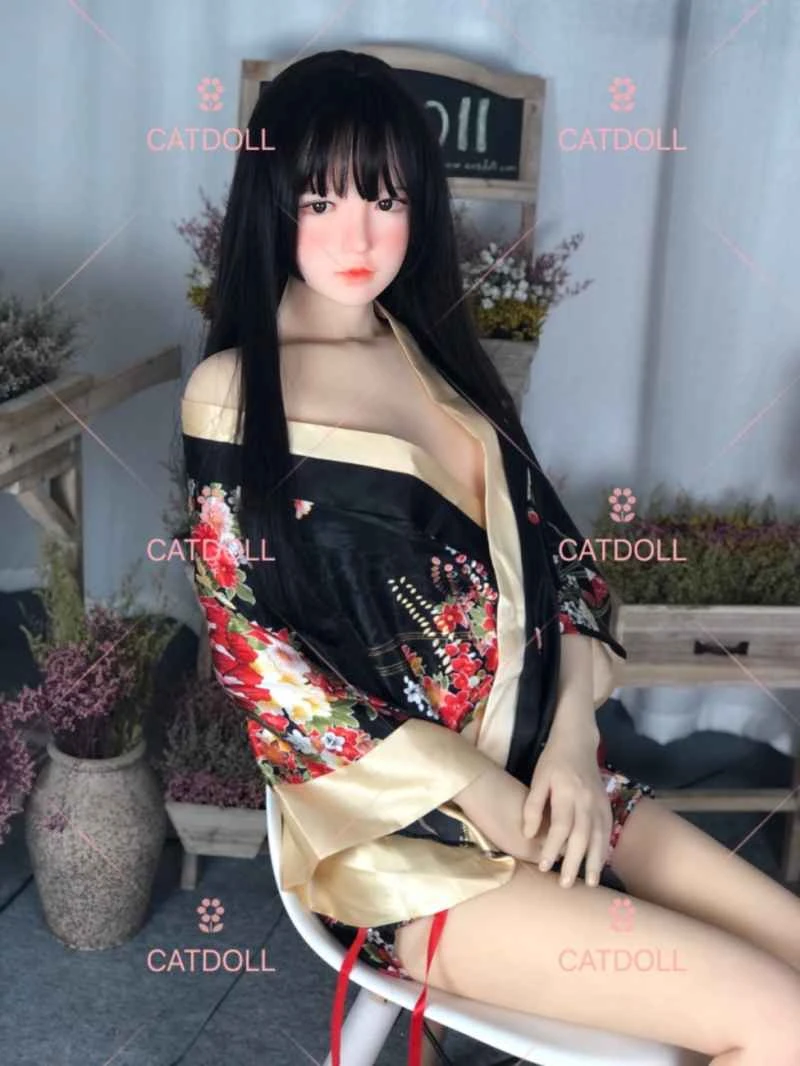
CATDOLL 146CM Jing TPE

Height: 146cm A-cup Weight: 26kg Shoulder Width: 32cm Bust/Waist/Hip: 64/54/74cm Oral Depth: 3-5cm Vaginal Depth: 3-15c...

Articles 2026-02-22