Read next
CATDOLL Himari TPE Head
This head is made of TPE material. This link can also be used to order any other TPE head. Just include the name of the...
Articles
2026-02-22
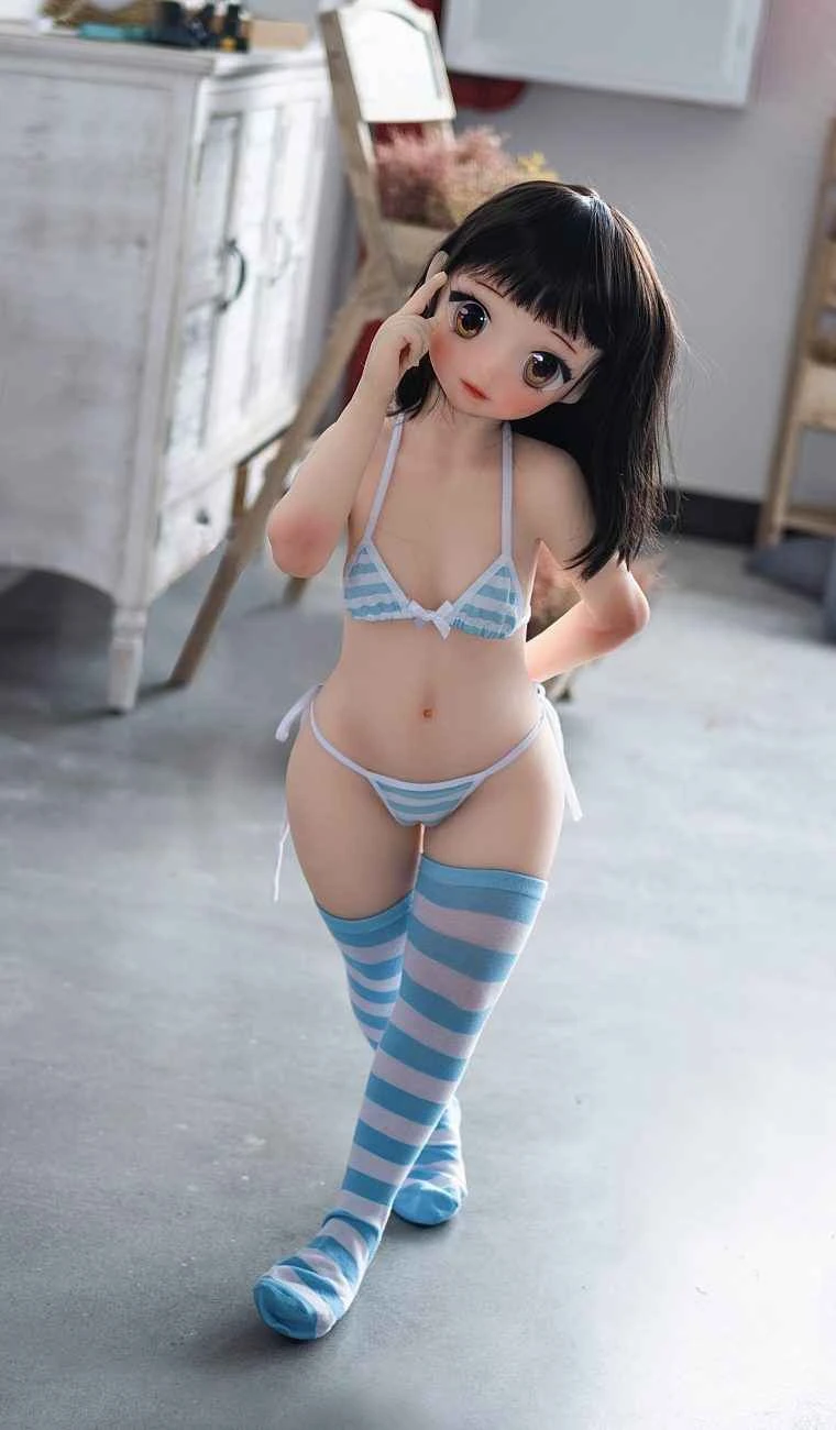
CATDOLL 101cm TPE Doll with Anime A-01-Type Head
Articles
2026-02-22

CATDOLL 146CM Ya TPE (Customer Photos)
Articles
2026-02-22

CATDOLL 146CM Miho TPE (Customer Photos)
Articles
2026-02-22