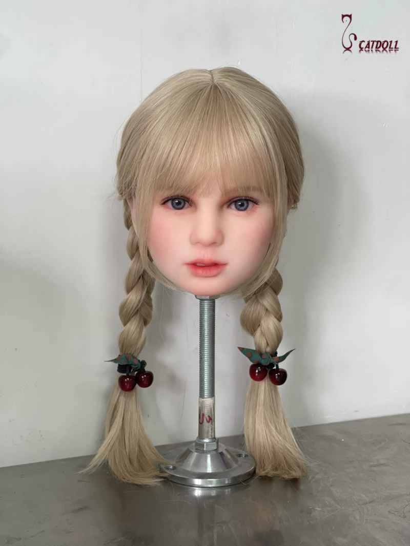
Implementation of DC monitoring system for substation
2026-04-06 05:50:54··#1
Abstract This paper proposes a system for remote monitoring of DC equipment in unmanned substations. Utilizing the substation's telephone channel, it enables remote monitoring of DC equipment, historical querying of DC equipment operation, and reporting of equipment malfunctions. The DC power supply in a power system consists of battery banks, charging equipment, and DC power panels. Its functions are: under normal conditions, to provide DC power for circuit breakers in the substation; and during faults, to provide working DC power for relay protection and automatic devices, circuit breaker tripping and closing, carrier communication, and plant machinery driven by DC motors in the power plant when power supply to the plant is interrupted. Its proper functioning directly affects the safe and reliable operation of the power system. Previously, each substation in the power system was staffed, allowing for regular inspections of the DC equipment's operating status, thus enabling timely detection and handling of abnormalities and ensuring the safe and stable operation of the substation. Currently, the power system is promoting unmanned substations. Although the dispatch center can obtain real-time information on substation operation through remote control channels, it can only obtain a limited amount of important information about the DC section (including: remote signaling quantities—AC power supply faults of chargers, charger faults, DC insulation grounding, abnormal DC power supply voltage; remote measurement quantities—control bus voltage). It cannot reflect detailed information about the DC system operation, especially in detecting situations where abnormal operation is just beginning. It only sends a message to the dispatch center when prolonged abnormal operation develops into a fault, by which time the incident has already escalated. If abnormal phenomena can be detected and addressed promptly when they first appear, the escalation of the abnormality can be prevented. Therefore, regular inspections by equipment maintenance personnel are necessary. Furthermore, the control of DC equipment operation is also performed on-site by maintenance personnel. With many substations and a limited number of maintenance personnel, it is clearly impossible to guarantee timely and sufficient completion of tasks. In this context, the DC monitoring system has emerged. Its main function is to upload DC equipment information from each substation to the monitoring center for querying, while the monitoring center can also send control commands to each station. In this way, maintenance personnel can not only remotely monitor DC equipment from the monitoring center, but also promptly detect abnormal operating conditions and handle them in a timely manner, preventing them from developing into accidents. Therefore, the establishment of a DC monitoring system can save manpower and resources and improve work efficiency. 1. Channel Selection Currently, various information sent from substations to the dispatch center, such as telemetry, remote signaling, remote control, main equipment status, and alarm information, is transmitted through remote control channels. This information has high real-time requirements, and it is undesirable for other information to occupy the channel and cause congestion, affecting the normal operation of dispatching. Therefore, the operating information of DC equipment must be transmitted remotely through another channel. Currently, in addition to the remote control channel, substations also have a telephone channel. This channel is generally used by staff working on-site, and by other auxiliary systems such as safety alarm systems when necessary. Usually, this channel is idle, but it is essential, so it can be used as the information channel for the DC monitoring system. The DC monitoring system has a small amount of data information, and the channel occupation time is short when transmitting. In this way, it can be dialed during work, occupy the channel, and hung up after work, sharing the channel with other systems in a time-sharing manner, thereby ensuring the normal operation of each system. 2 System Composition The monitoring center computer connects to the telephone network via a modem. The monitors also connect to the telephone network via modems. Both modems can call each other, establishing a communication link through their respective modems and the telephone network to exchange information. In this way, the monitoring center computer can use this communication link to collect information from each station's monitors, send control commands, and each station's monitors can also report daily scheduled operating data and abnormal situation information to the center. The system consists of three parts: the monitors are the front-end system, responsible for collecting equipment data, controlling operating status, and transmitting information; the monitoring center is the back-end system, running on a PC, responsible for sending commands to all substation monitors, receiving their operating data, and processing and analyzing the data; data communication between the two relies on modems and the telephone network. The monitoring center and monitors form a one-to-many system. 3 Monitor Design 3.1 Monitor Principle The monitor is a system installed in each substation. It collects operating status information from each DC device, controls it, and transmits the data to the monitoring center and other monitoring units. The monitor is designed using an industrial control computer. Its I/O ports are used for input and output. It can directly acquire measured quantities, status quantities, and battery insulation status information from DC equipment. It can also control and regulate DC equipment, such as the on/off operation of the charger, changes in equalization and float charging, changes in equalization and float charging voltage, and the opening and closing of feeders. On the other hand, the microcomputer controller sends remote control signals to the RTU or dispatch center via RS232 or modem, and transmits the operating information of all DC equipment to the monitoring center where the equipment maintenance personnel are located via the modem and telephone network. 3.2 Monitor Software Design The monitor software consists of four modules: a communication module, a data transceiver module, an I/O module, and a data processing module. The communication module prepares for communication for data transmission, including turning the modem on and off and automatic dialing functions. The software is set to turn the modem on and off at regular intervals, which allows this system to share the telephone channel with other systems such as alarm systems. Automatic dialing automatically connects to the monitoring center's modem when an abnormal event occurs in the DC equipment, sending the corresponding alarm information. The data transceiver module is primarily responsible for data transmission and reception after the communication link is established. Transmitted data includes: current operating information of each DC device; historical data stored in the monitor for a fixed time within 24 hours; and all alarm information within 24 hours. Received data includes control and adjustment commands from the monitoring center. The I/O module functions include: providing the monitor's human-machine interface, collecting data from each DC device, and controlling it. The data processing module is the core module of the monitor. On one hand, it processes the data acquired by the I/O module and stores daily data in the database according to set time intervals, ready for transmission to the monitoring center by the data transceiver module. This data is updated daily. On the other hand, it analyzes the control commands received by the transceiver module and provides control information to the I/O module. 4. Monitoring Center Design The monitoring center is a microcomputer running the monitoring center's backend software. The monitoring center software mainly includes four parts: a communication module, a database generation module, a main control module, and a report printing module. The communication module functions similarly to the monitor's communication module, establishing a communication link by connecting to the substation's monitor modem and sending control commands. It can also be connected to and receive information uploaded by other devices. Developed using Visual Basic 5.0, this module only needs to establish a communication link by connecting to the modem. The specific data transmitted is irrelevant and handled by the main control software. The data processing module serves two purposes: first, it creates a database of information for each substation's DC equipment; second, it organizes and stores the daily data collected from each substation into a historical database of all substation DC equipment. Users can flexibly create databases for each substation and all its DC equipment according to their needs, and maintain all substation information automatically after maintenance. This system offers high flexibility and ease of operation. Furthermore, each substation monitor regularly uploads its daily data to the monitoring center, which then stores it in its respective database based on the substation name, forming a historical database for use by the report printing system. The main control software provides a human-machine interface based on the Windows 95 operating system, allowing users to operate the on-screen graphics using a mouse and keyboard. By simply clicking on the corresponding graphic element of a device component with the mouse, one can query and control that device. Alternatively, one can input device parameters using the keyboard to remotely adjust its operating parameters. Maintenance personnel can query and control equipment within the operating station using both mouse and keyboard. Once the communication module establishes a communication link, it can open remotely transmitted data, display it on the screen, and then pass this data to the data processing module.